Endoscopic gastric constriction device

a gastric bypass and endoscopic technology, applied in the field of gastric bypass devices, can solve the problems of stomach perforation, high cost of surgical procedures, and substantial risks for patients

Inactive Publication Date: 2005-06-30
INTRAPACE
View PDF3 Cites 117 Cited by
  • Summary
  • Abstract
  • Description
  • Claims
  • Application Information

AI Technical Summary

Benefits of technology

[0009] Accordingly, it would be desirable to provide a l

Problems solved by technology

These surgical procedures are expensive and create substantial risks to the patient either during surgery, in recovery or with respect to subsequent failure of the procedure.
However, the Lap Band® proced

Method used


Image

  • Endoscopic gastric constriction device
  • Endoscopic gastric constriction device
  • Endoscopic gastric constriction device

Examples


Embodiment Construction

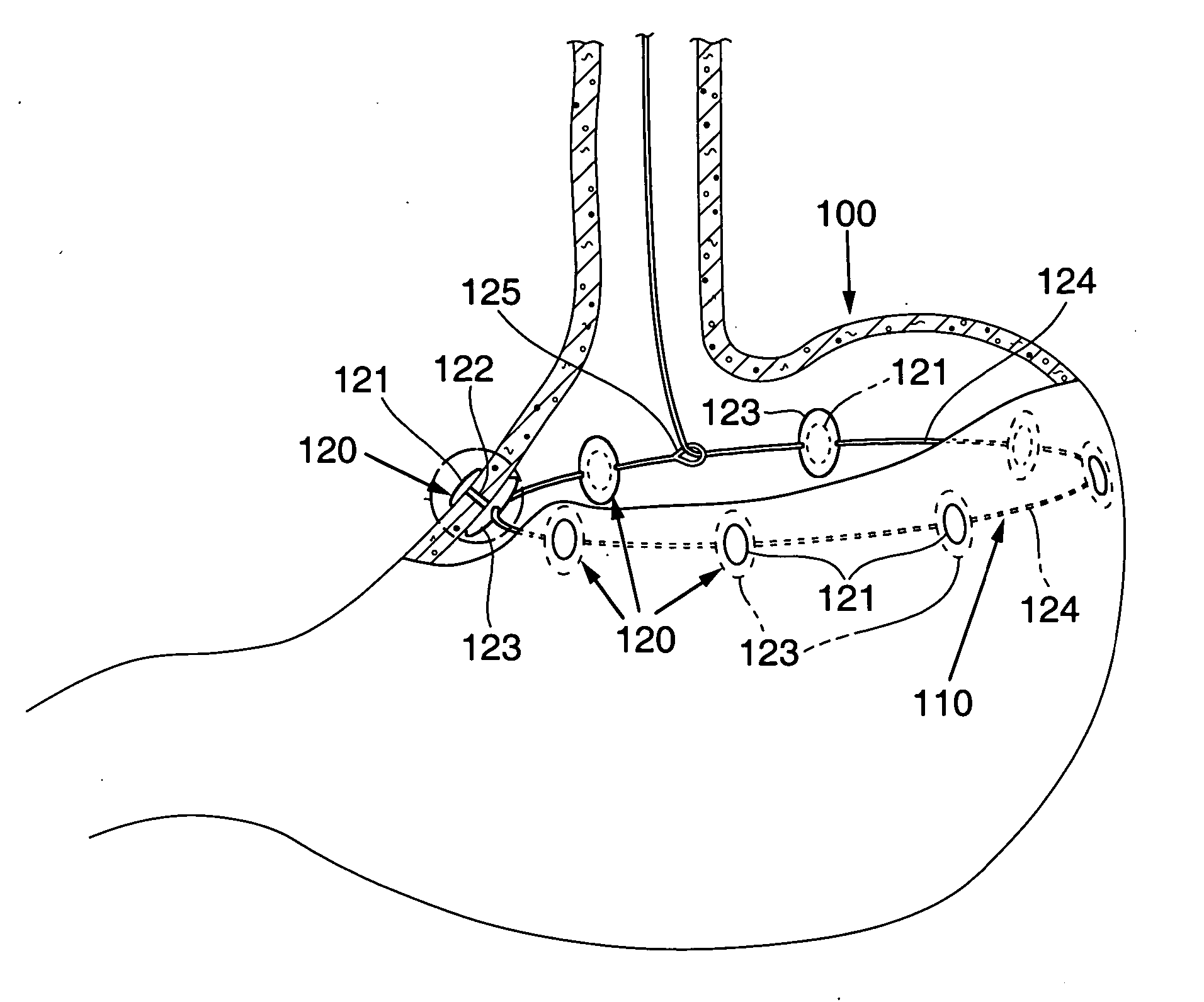
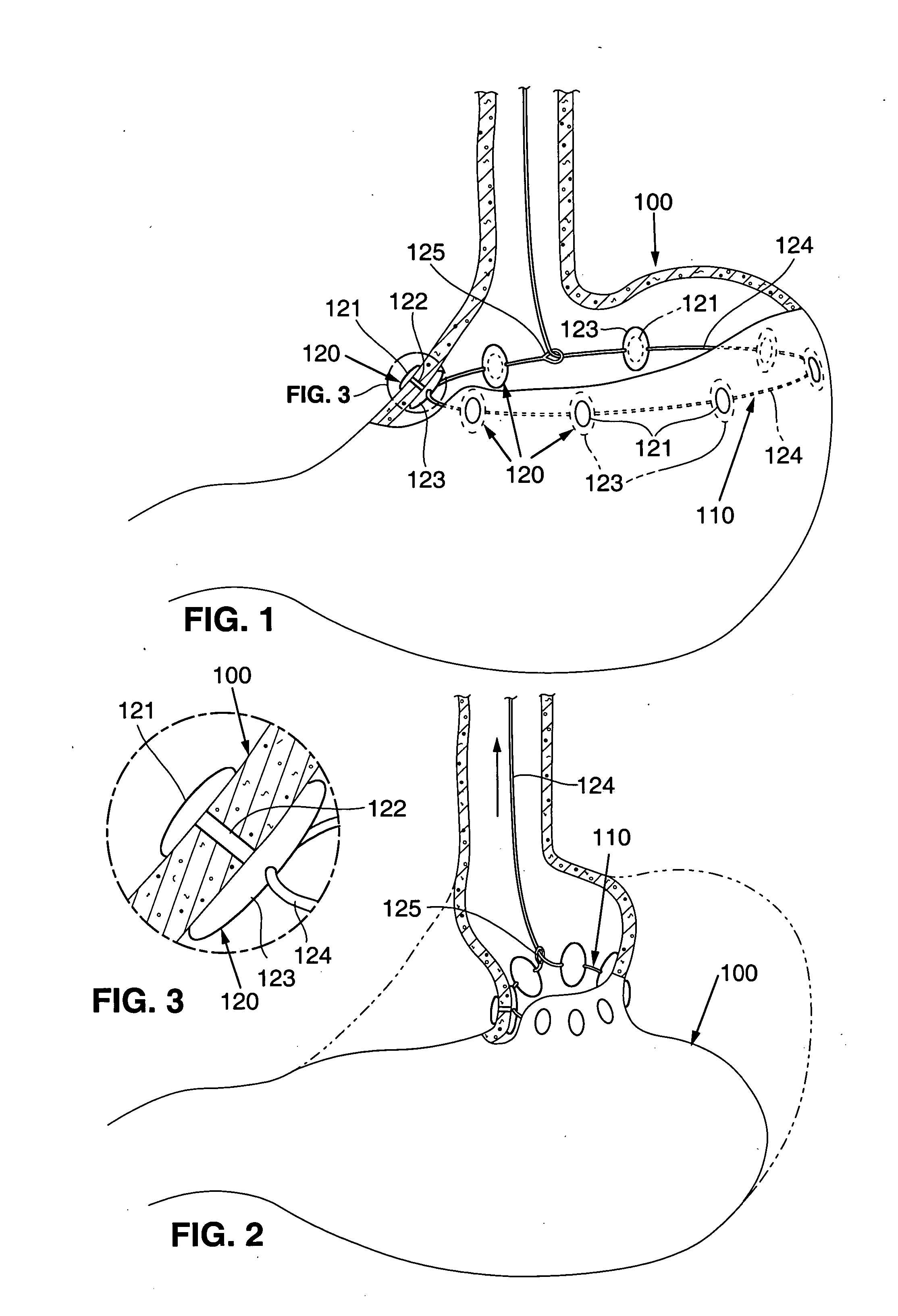
[0022] Referring to FIGS. 1-3 a device 110 in accordance with the invention is illustrated. The device 110 comprises a plurality of anchors 120 attached to the wall of a stomach 100.

[0023] As illustrated in FIG. 3, each anchor 120 comprises an end portion 121 configured to interface with the outside of the stomach wall hold the anchor 120 in place. The end portion 121 has a sufficient surface area with respect to forces applied to the anchor to prevent device pull out. An elongate portion 122 extends from the end portion 121 into the stomach 100. A connecting device 123 is coupled inside the stomach to the elongate portion 122.

[0024] As illustrated in FIG. 1, a tether 124 extends through each connecting devices 123 (e.g., through a hole). The tether 124 is then joined in a loop with one end of the tether extending through a loop 125 in the other end of the tether and extending out of the stomach.

[0025] As illustrated in FIG. 2, the tether 124 used to draw the stomach wall togethe...


PUM


Abstract

An endoscopically implantable device is provided that cinches the stomach together to create a reduced diameter for a portion of the stomach. The device may be, for example, a gastrorestrictive device used to treat overweight or obese patients. The device may be used, for example, to treat gastroesophogeal reflux disease (GERD).

Description

RELATED APPLICATION DATA [0001] This application is a continuation in part of U.S. application Ser. No. 10 / 295,115, filed Nov. 14, 2002, which is a divisional of U.S. application Ser. No. 09 / 847,884 filed May 1, 2001 all of which are incorporated herein by reference.FIELD OF THE INVENTION [0002] The invention relates to a gastric constriction device for restricting the diameter of a portion of a stomach or creating a small pouch in the stomach. BACKGROUND [0003] A variety of devices and techniques have been used to surgically alter the digestive tract of a patient in order to treat obesity and related diseased. The techniques include creating a small pouch in a patient's stomach that restricts emptying(restrictive procedures), bypassing a portion of the digestive tract, e.g. or the stomach or small intestines (malabsorptive procedures), or a combination of both. [0004] Most of these techniques involve substantial surgery where portions of the stomach are stapled closed and / or where ...

Claims


Application Information

Patent Timeline
IPC IPC(8): A61B17/00A61F5/00A61M25/02A61N1/36
CPCA61B17/00234A61N1/36007A61B17/12013A61B2017/00004A61B2017/00017A61B2017/00026A61B2017/00084A61B2017/00477A61B2017/00827A61B2017/0404A61B2017/0414A61B2017/0496A61B2017/06176A61F5/0003A61F5/0086A61M25/02A61M2025/0233A61M2025/028A61B17/0401
Inventor IMRAN, MIR A.
Owner INTRAPACE
Why Eureka
Try Eureka