Support for real-time queries concerning current state, data and history of a process

Inactive Publication Date: 2005-06-30
MICROSOFT TECH LICENSING LLC
View PDF4 Cites 5 Cited by
  • Summary
  • Abstract
  • Description
  • Claims
  • Application Information

AI Technical Summary

Benefits of technology

[0016] In a fourth aspect, the invention provides a data processing system for monitoring and reporting process state data pertaining to instances of a process represented within a stored workflow representation. The system includes at least one data storage device having the workflow representation stored thereon. A queryable database having a schema established based upon a tracking profile is provided. The tracking profile is based on one or more selected portions of the stored workflow representation. A monitoring means is provided for monitoring process state data pertaining to instances of the process. Monitoring is performed within parameters established by the tracking profile. The monitoring means is further for writing the process state data to the database in accordance with the database schema. A reporting means is provided for selectively reporting process state data written to the database, in accordance with parameters established by the tracking profile. Preferably, the system is further for monitoring and reporting payload data pertaining to instances of the process represented by the stored workflow representation. In this implementation, the tracking profile is further based on items of payload data from a message schema associated with the stored workflow representation. The monitoring means is further for monitoring payload data pertaining to instances of the process, within parameters established by the tracking profile, and for writing the payload data to the database, in accordance with the database schema. The reporting means is further for selectively reporting payload data written to the database, in acco

Problems solved by technology

However, current known workflow monitoring systems, including Microsoft Corporation's BizTalk™

Method used


Image

  • Support for real-time queries concerning current state, data and history of a process
  • Support for real-time queries concerning current state, data and history of a process
  • Support for real-time queries concerning current state, data and history of a process

Examples


Embodiment Construction

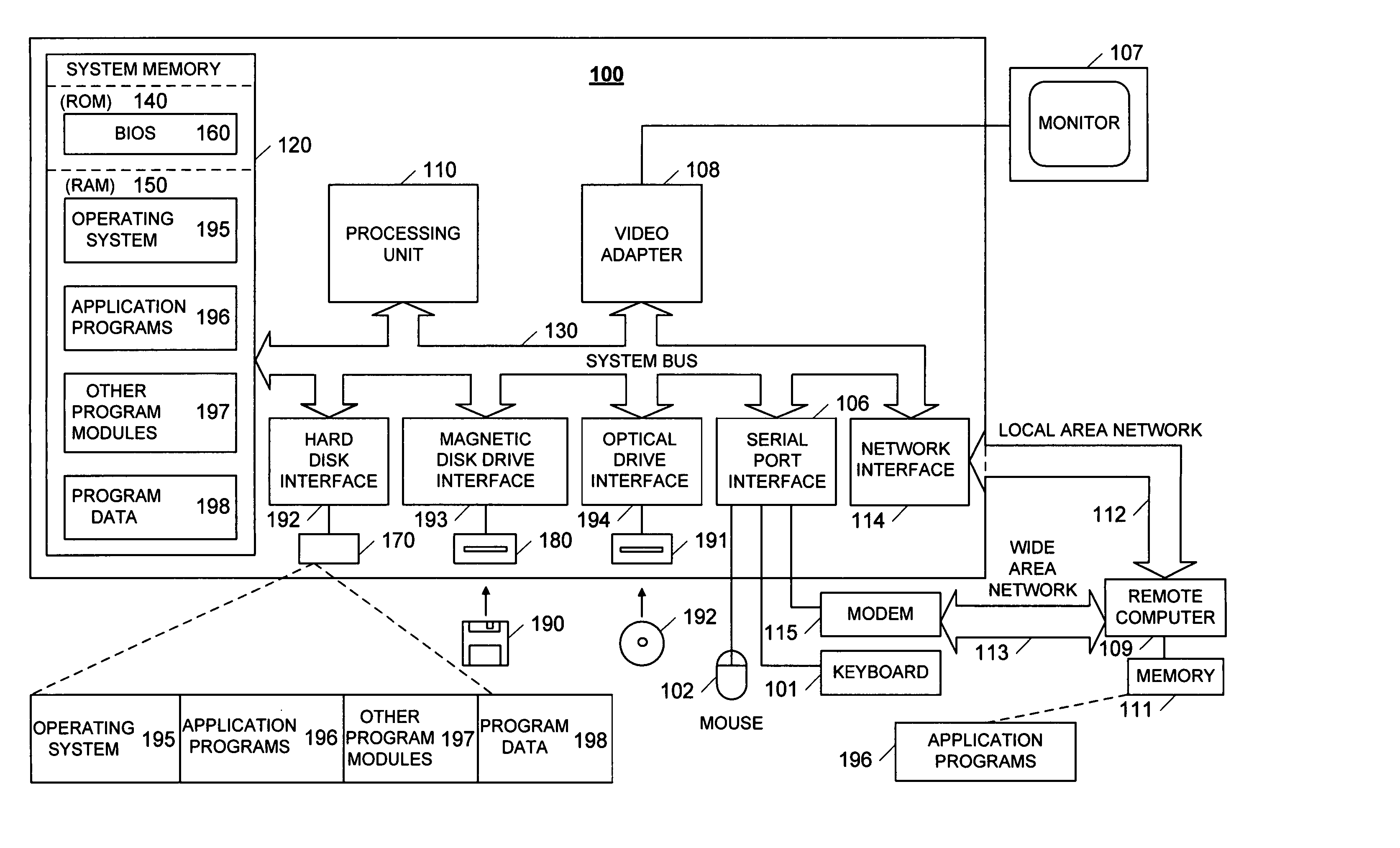
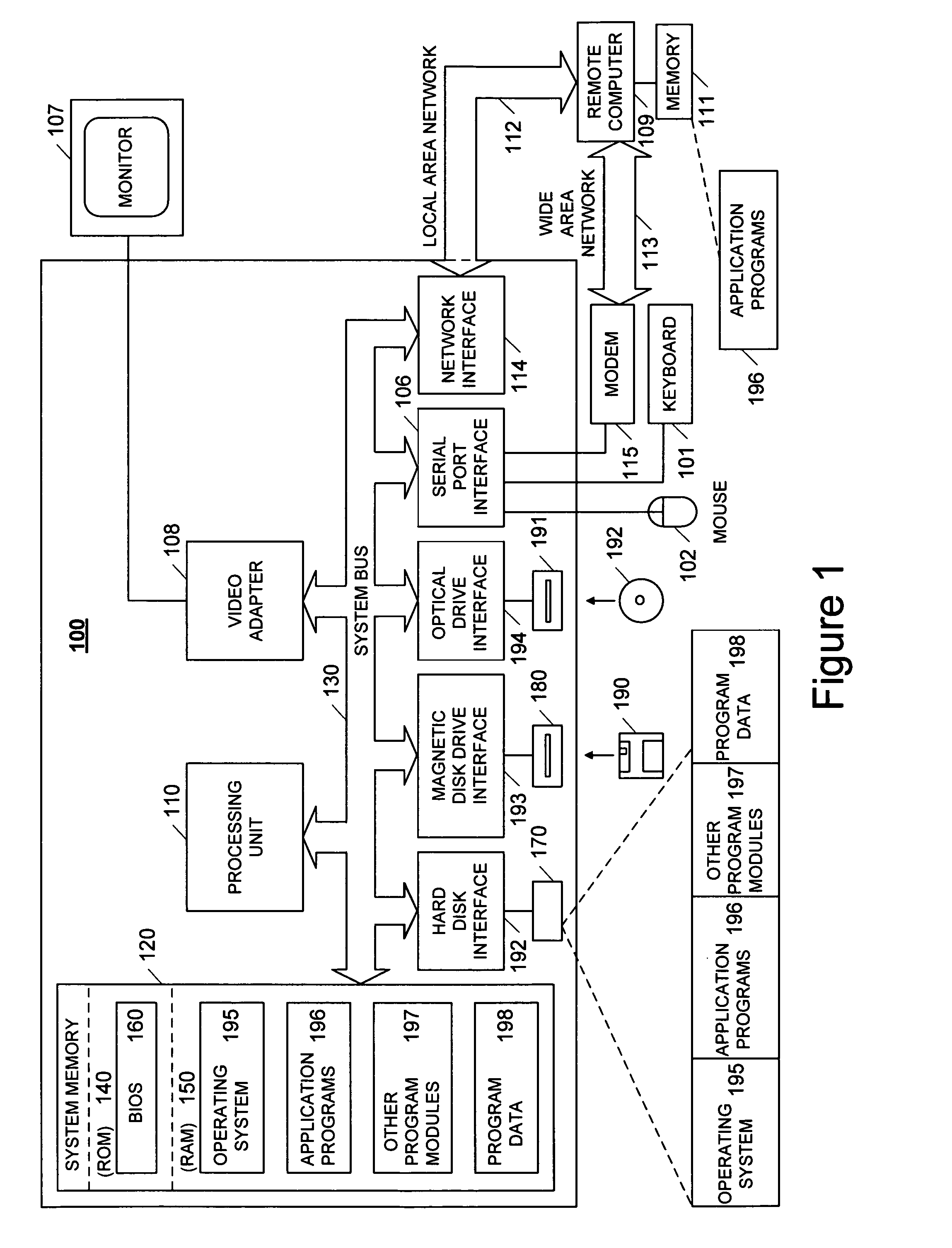
[0052] Exemplary Operational Environment

[0053] The conventional general-purpose digital computing environment illustrated in FIG. 1 can be used to implement various aspects of the invention. Computer 100 includes a processing unit 110, a system memory 120 and a system bus 130 that couples various system components including the system memory to the processing unit 110. System bus 130 may be any of several types of bus structures including a memory bus or memory controller, a peripheral bus, and a local bus using any of a variety of bus architectures. System memory 120 includes a read only memory (ROM) 140 and a random access memory (RAM) 150.

[0054] A basic input / output system (BIOS) 160 containing the basic routines that help to transfer information between elements within the computer 100, such as during start-up, is stored in ROM 140. Computer 100 also includes a hard disk drive 170 for reading from and writing to a hard disk (not shown), a magnetic disk drive 180 for reading fr...


PUM


Abstract

A computer-implemented method is provided for defining interesting portions of a workflow of a business or other type of process. Using a tracking profile editor, a portion of a given workflow is selected and associated with a named process part. Items of payload data to be used in reports are selected from a message schema associated with the given workflow. A profile is generated based on the given workflow and the selected items of payload data. A tracking profile compiler receives the created tracking profile and generates a star schema, a flattened view and OLAP cube based on the tracking profile. An interceptor extracts monitored workflow events and stores event information to a tracking stream, based on the tracking profile. A tracking service extracts information pertaining to the monitored events from the tracking stream and stores the information in the queryable database. The OLAP cube and the flattened view are updated based on the information written to the queryable database.

Description

CROSS REFERENCE TO RELATED APPLICATIONS [0001] This application is a continuation of prior U.S. patent application Ser. No. 10 / 157,968, filed May 31, 2002, the entire contents of which are incorporated herein by reference. [0002] A portion of the disclosure of this patent document contains material which is subject to copyright protection. The copyright owner has no objection to the facsimile reproduction by anyone of the patent document or the patent disclosure, as it appears in the Patent and Trademark Office patent file or records, but otherwise reserves all copyright rights whatsoever.FIELD OF THE INVENTION [0003] The present invention relates to methods and computer systems for monitoring a workflow representing a business or other type of process. More particularly, the present invention relates to methods and computer systems for monitoring such a workflow and allowing a user to formulate queries and receive information related to execution of specific portions of the workflo...

Claims


Application Information

Patent Timeline
IPC IPC(8): G06F7/00G06F17/00G06Q10/06
CPCG06Q10/06
Inventor CHKODROV, GUEORGUIJASON, ZACHCLARK, WAYNE A.YILDIRIM, TOLGACHAO, LUCYNG, ANDREW
Owner MICROSOFT TECH LICENSING LLC
Why Eureka
Try Eureka