
Security verification method and device

a security setting and verification method technology, applied in the field of security setting verification, can solve problems such as malicious operations, misappropriation of confidential files, and serious security problems, and achieve the effect of rigorous verification of security settings

Inactive Publication Date: 2005-06-30
NEC CORP
View PDF3 Cites 56 Cited by
  • Summary
  • Abstract
  • Description
  • Claims
  • Application Information

AI Technical Summary

Benefits of technology

[0019] It is an object of the present invention to provide a verification method and device that are capable of solving the above-described problems and rigorously verifying security settings.
[0020] It is another object of the present invention to provide a method and device that are capable of examining the presence or absence of problems that are caused by the compound action of a plurality of security settings.
[0021] It is yet another object of the present invention to provide a method and device that are capable of reducing the load imposed upon the object system, i.e., the object of examination or verification, at the time of inspection.
[0028] According to the present invention, data transfer paths that represent data movement in an object system, i.e., a computer that is the object of examination or verification, are compared with security verification policies in which the paths of data movement that is improper from the standpoint of security have been set, and the existence of improper settings, which are composite errors of the security settings in an object system, can therefore be easily verified. In addition, the inclusion of a configuration for searching for improper settings, which are composite errors, enables security settings that are the source of improper settings to be singled out, and further enables an acceleration of the correction of settings. Still further, the present invention is realized only as a configuration for collecting setting information that relate to security, i.e., security setting information, from the object system without resorting to measures that would increase load such as a pseudo-attack, and thus is capable of verification while imposing little load on the object system.

Problems solved by technology

In particular, servers that are open to the public on the Internet accept requests from users of the general public and are therefore prone to so-called “cyber-attacks,” i.e., attacks on cyberspace, and this vulnerability poses a serious security problem.
In this type of cyber-attack on a public server, individuals take improper advantage of security holes such as vulnerable points and improper settings that exist in the server to submit malicious requests, activate illegal operations, and bring about malicious operations such as the misappropriation of confidential files.
Examples that can be offered of vulnerable points that exist in a server include programming errors that cause faults in the server software, and examples that can be offered of improper settings include setting errors that occur when making security settings that cause faults in the server software.
However, completely eliminating security holes in software is extremely difficult, and in practical terms, impossible.
In addition, since software creators and server operators are not typically the same entity, the possibility cannot be excluded that a server operator will misunderstand the software specifications and thus make settings in the software that will jeopardize security.
One is a vulnerability that allows user privileges to be misappropriated through the Internet; and the other is a vulnerability that allows any user to assume an administrators authority.
None of the above-described examples of the prior art takes the content of security settings as the object system, and these examples of the prior art therefore suffer from the problem of the inability to investigate whether the security settings are improper settings.
In other words, in each of the above-described examples of the prior art, a pseudo-attack cannot be carried out for examining security settings.
As a result, only vulnerabilities for which an attack procedure can be produced in advance are taken as the inspection items, and security settings for which a pseudo-attack cannot be prepared cannot be examined.
In other words, this method can take as inspection items only obvious setting errors that can be examined for individual settings, such as cases in which the password is vacant, and cannot examine the existence of improper settings that are based on composite setting errors that are difficult to determine as a setting error in isolation.
Each of the above-described examples of the prior art suffers from the problem of the inability to determine whether the combination of a plurality of security settings will result in an improper setting.
None of the above-described examples of the prior art is capable of examining the existence of improper settings that result from composite setting errors.
These examination devices are therefore incapable of detecting a case in which each individual setting taken by itself cannot be viewed as an error and is thus determined not to constitute a security hole but in which the combination of these security settings results in a security hole of the computer system.
Each of the above-described devices of the prior art further suffers from the problem of imposing a high burden upon the object system.
In this method, an attack that uses a vulnerability is actually delivered, and the object system is therefore subjected to a load that is equivalent to an actual attack, and the object system may in some cases actually fail as a result.
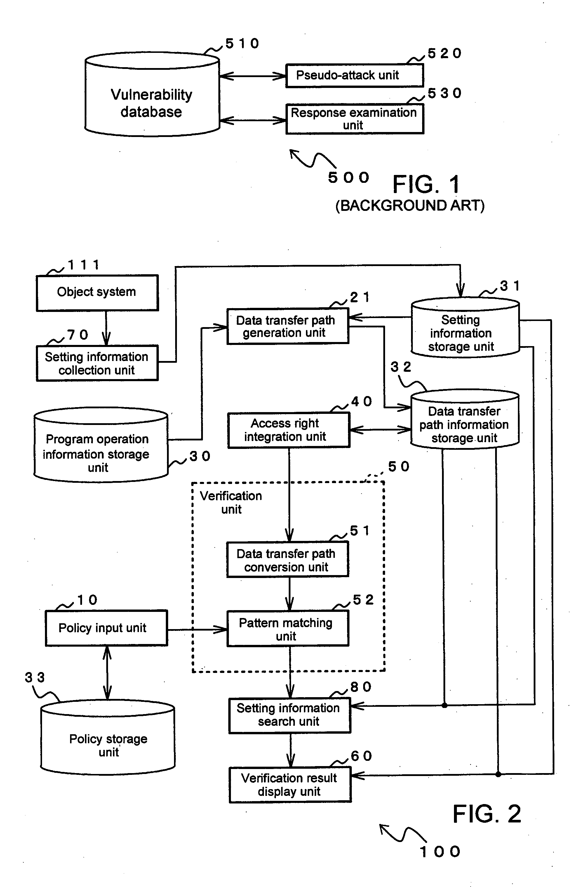
Accordingly, the security examination device shown in FIG. 1 may in some case not be applicable due to the state of the object system.

Method used


Image

  • Security verification method and device
  • Security verification method and device
  • Security verification method and device

Examples


first embodiment

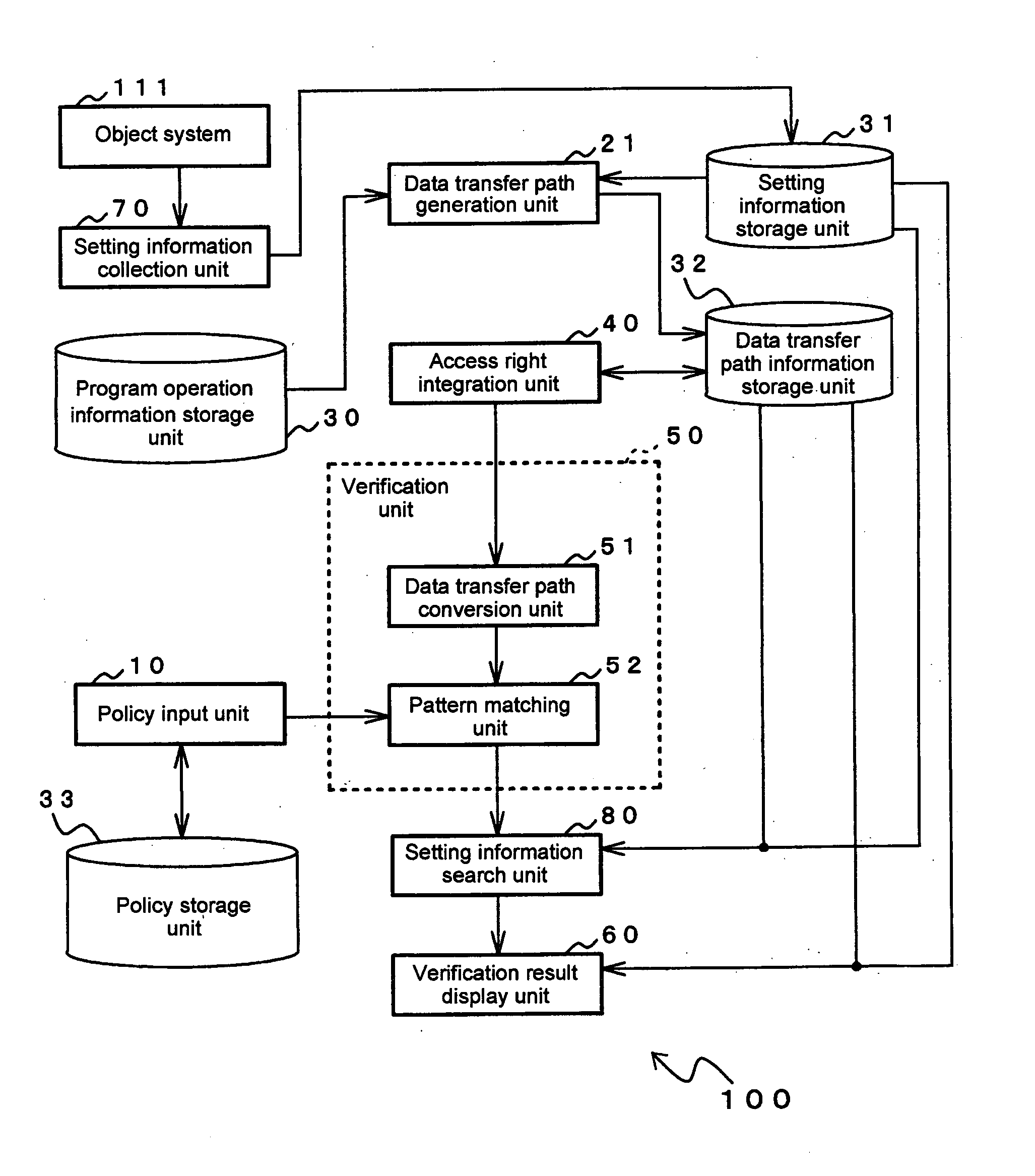
[0095]FIG. 2 shows the configuration of security verification device 100 according to the first embodiment of the present invention. As shown in FIG. 2, security verification device 100 verifies the security settings of object system 111 and is provided with: policy input unit 10, data transfer path generation unit 21, program operation information storage unit 30, setting information storage unit 31, data transfer path information storage unit 32, policy storage unit 33, access right integration unit 40, verification unit 50, verification results display unit 60, setting information collection unit 70, and setting information search unit 80.

[0096] Object system 111 is a computer that is the object of verification for errors in security settings by security verification device 100. More specifically, object system 111 corresponds to, for example, an OS (operating system), a web server application, or a web client application.

[0097] Setting information collection unit 70 collects f...

second embodiment

[0158]FIG. 7 shows an example of the configuration of security verification device 100a according to the second embodiment of the present invention. In the following explanation, parts that have the same composition and perform the same processes as in security verification device 100 in the above-described first embodiment are given the same reference numerals and detailed explanation of these portions is abbreviated.

[0159] As shown in FIG. 7, security verification device 100a according to the second embodiment verifies the security settings of object system 111, and includes: setting information collection unit 70, setting information storage unit 31, program operation information storage unit 30, data transfer path generation unit 21, data transfer path information storage unit 32, access right integration unit 40, and data transfer path display unit 90.

[0160] Data transfer path display unit 90 is constituted by a display device such as a liquid crystal display device and has t...

third embodiment

[0165]FIG. 9 shows an example of the configuration of security verification device 100b according to the third embodiment of the present invention. In the following explanation, parts that have the same composition and perform the same processes as in security verification device 100a in the previously described second embodiment are given the same reference numerals and detailed explanation of these parts is here abbreviated.

[0166] Security verification device 100b according to the third embodiment is similar to security verification device 100a according to the second embodiment but differs in that access right integration unit 40 is not provided.

[0167] In the present embodiment, data transfer path display unit 90 implements screen display of the data transfer paths that are indicated by the data transfer path information that has been generated by data transfer path generation unit 21.

[0168] The third embodiment is thus configured to collect the security setting information of...


PUM


Abstract

A security verification method for verifying whether improper settings that indicate composite errors of security settings exist in an object system, which is an object of examination, includes steps of: reading data transfer paths that represent data movement in the object system and that are generated based on program operation information that describes operations of a program that is used in the object system, integrating the access rights of data transfer paths that have been read; and searching for improper paths among the data transfer paths for which access rights have been integrated based on security verification policies in which improper paths, which are paths of data movement that are improper from the standpoint of security, have been set in advance.

Description

BACKGROUND OF THE INVENTION [0001] 1. Field of the Invention [0002] The present invention relates to the verification of the security settings of software, and more particularly to a security verification method and device that can detect and indicate the presence of composite errors in security settings that can become security holes in software. [0003] 2. Description of the Related Art [0004] With the popularization of the Internet in recent years, the Internet is becoming a vital element of the social infrastructure that rivals the telephone network or the like. Users can receive a great variety of services on the Internet. Services that are offered on the Internet are typically realized by accepting a series of requests from a user, executing processing in accordance with the received requests that have been accepted, and then sending the results of this processing to the user. More specifically, services are widely disseminated by means of WWW (World Wide Web), and these serve ...

Claims


Application Information

Patent Timeline
IPC IPC(8): G06F12/14G06F1/00G06F11/36G06F15/00G06F21/00G06F21/12G06F21/60H04L9/00H04L29/06
CPCG06F21/55H04L63/20G06F21/577
Inventor SAKAKI, HIROSHIISHIHARA, YASUNORIFUJIWARA, TORUYOSHIDA, MAKI
Owner NEC CORP
Learn More