Combined aircrew systems tester (cast)

a combined aircrew and system tester technology, applied in the field of combined aircrew systems testers, can solve the problems of expensive and awkward for users to test their equipment, inability to control the aircraft, and inability to use the power source of such equipmen

Inactive Publication Date: 2005-07-07
SCOT
View PDF14 Cites 19 Cited by
  • Summary
  • Abstract
  • Description
  • Claims
  • Application Information

AI Technical Summary

Benefits of technology

[0010] It is therefore an object of the present invention to have an integrated unit that can functionally test the various aircrew equipment.

Problems solved by technology

If any of the above systems do not work, a pilot for instance may be unable to control the aircraft.
This is expensive and very awkward for users to test their equipment at different stations while for instance they are wearing such equipment.
Moreover, the power sources for such equipment are usually not commonly available because of the high power necessary to drive such complicated devices.
It is awkward for users to bring the tester and the separate high pressure source.

Method used


Image

  • Combined aircrew systems tester (cast)
  • Combined aircrew systems tester (cast)
  • Combined aircrew systems tester (cast)

Examples


Embodiment Construction

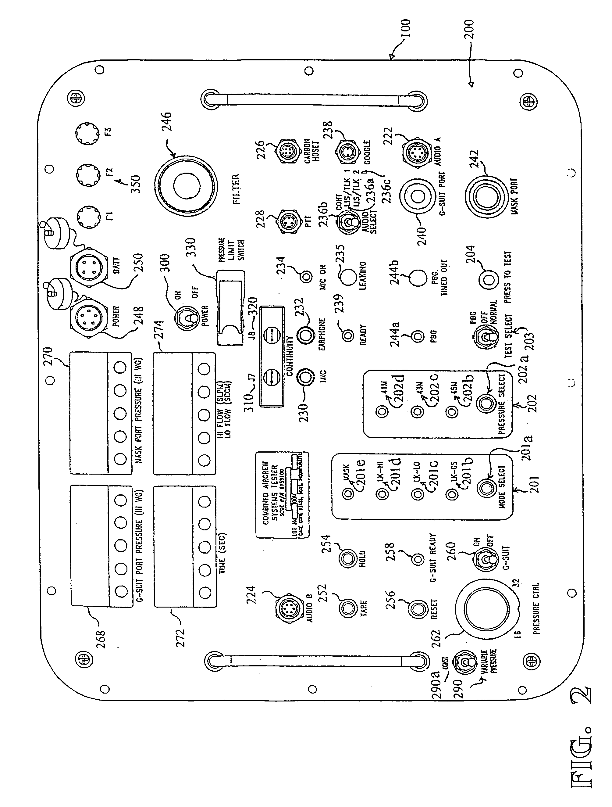
[0026] The present invention is an integrated unit that can functionally test the various aircrew equipment. Life support systems include COMBAT EDGE (combined advanced technology enhanced design G-ensemble) system components. The system includes the MBU-20 / P Oxygen Mask, CSU-17 / P Vest Assembly, HGU-55 / P Helmet with occipital bladder, CRU-94 / P Integrated Terminal Block or PBG (pressure breathing for Gs) Chest Mounted Regulator or both CRU-94 / P Integrated Terminal Block and PBG Chest Mounted Regulator, and all associated Anti-G garments.

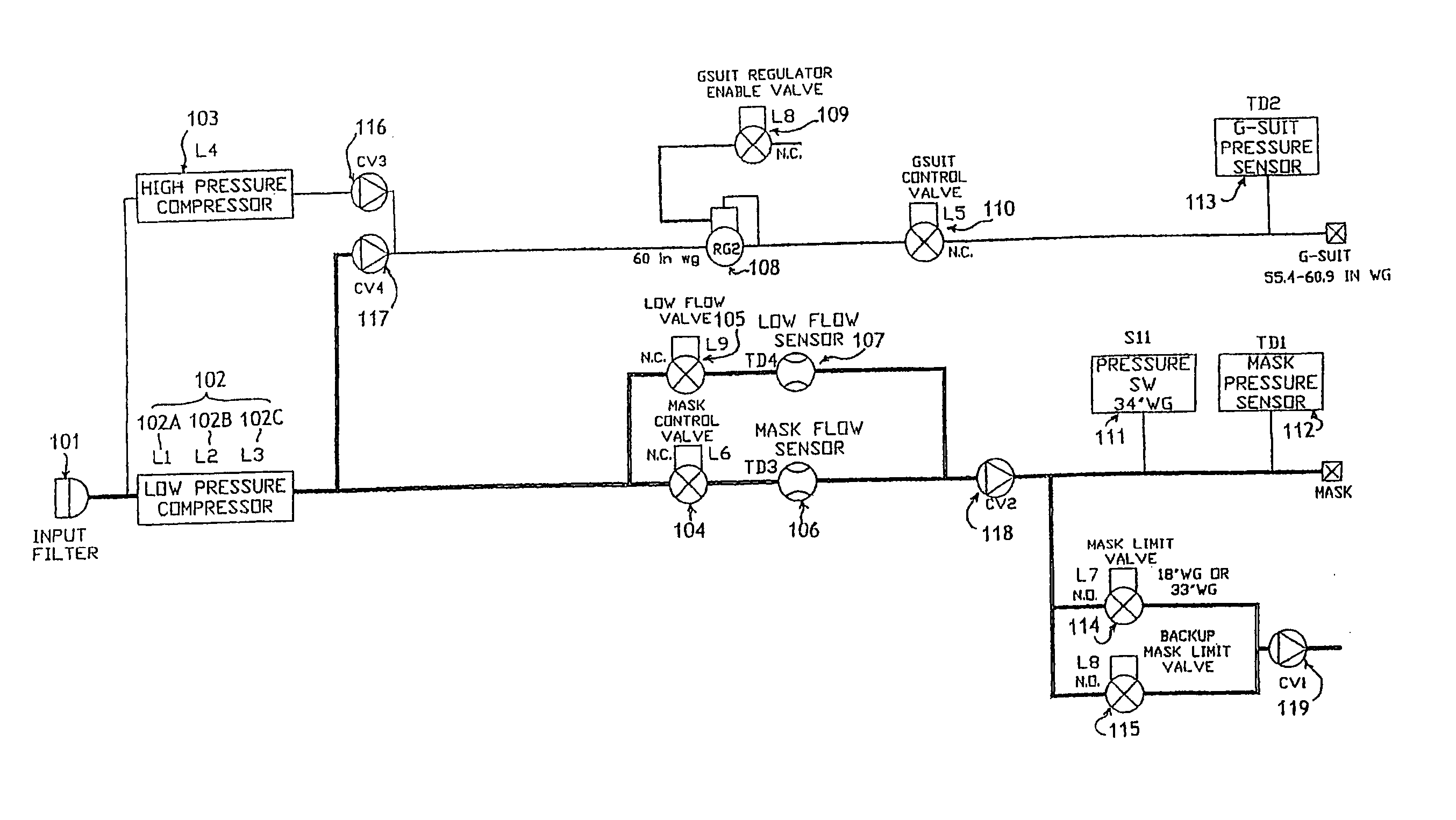
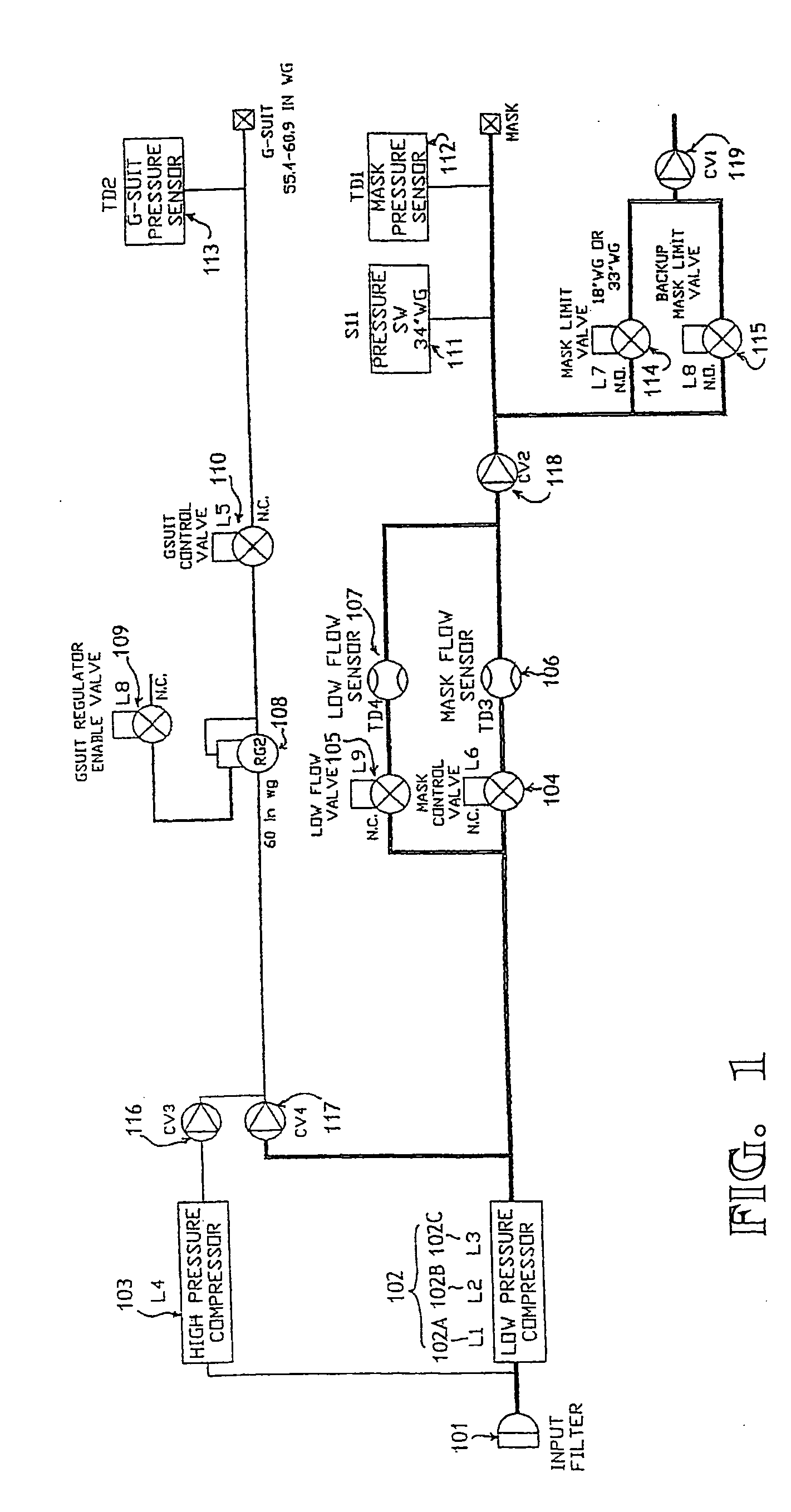
[0027] A functional diagram of a gas system for a combined aircrew system tester (CAST) is shown in FIG. 1.

[0028] The gas system of the tester provides two air sources. One is for a mask or a vest, and the other is for a G-suit (a suit designed to counteract the physiological effects of acceleration on an aviator or astronaut—called also called an anti-G suit). The air for the G-suit is provided through a G-suit port and the air for the mask / vest th...


PUM


Abstract

The present invention enables functional testing nearly all aircrew equipment including a COMBAT EDGE (combined advance technology enhanced design “G” ensemble) system of components which include a mask, a G-suit, communication systems, and a goggle. The present invention includes a gas system which includes an input filter (101), a first compressor (102) comprising at least one blower, preferably three blowers connected in series, a second compressor (103), a first flow sensor (106), a second flow sensor (107), a first flow valve (104), a second flow valve (105), a regulator (108), a first pressure sensor (112), a second pressure sensor (113), a first pressure valve (110), a second pressure valve (114), and a controller. The inlet filter (101) is designed to accept a chemical filter. The second compressor (103) produces a lower flow at a higher pressure than the first compressor (102). This combination works particularly well when inflating the G-suit because when the G-suit inflates, initially there is a large change in volume without much change in pressure, and then, as the G-suit fills out and becomes firm, the chance in volume slows down and the rate of the pressure increases. The present invention includes a digital indicator. A method of operating the tester and the gas system are also disclosed. The present invention includes a normal breathing test, a preflight test, a G-suit leak test and two dynamic flow leak tests. The communication system test and goggle test are further included.

Description

CLAIM OF PRIORITY [0001] This application makes reference to, incorporates the same herein, and claims all benefits accruing under 35 U.S.C. §119 from a provisional application entitled Combined Aircrew Systems Tester (CAST) filed in the United States Patent & Trademark Office on 1 Aug. 2001, and there duly assigned Ser. No. 60 / 308,846 and my U.S. patent application entitled COMBINED AIRCREW SYSTEMS TESTER (CAST) filed in the United States Patent & Trademark Office on 31 Jul. 2002, and there duly assigned Ser. No. 10 / 208,188 by that Office.BACKGROUND OF THE INVENTION [0002] 1. Field of the Invention [0003] The present invention relates to a combined aircrew systems tester, and more particularly, to a combined aircrew systems tester enabling functional testing of aircrew equipment. [0004] 2. Description of the Background Art [0005] Life support systems are very crucial for members of an aircrew of aircraft and especially high performance aircraft. Life support systems include COMBAT ...

Claims


Application Information

Patent Timeline
Patent Type & Authority Applications(United States)
IPC IPC(8): A62B7/00A62B17/00A62B27/00B64D10/00
CPCB64D10/00A62B27/00
Inventor JORDAN, CLIFFORD L.
Owner SCOT
Why Eureka
Try Eureka