Floating-type brake disk

a technology of brake discs and rotors, applied in the direction of brake discs, braking elements, braking members, etc., can solve the problems of increased increased parts number, etc., to reduce the number of parts, reduce assembling man-hour and cost, and improve the heat lowering property of the rotor

Inactive Publication Date: 2005-07-07
YUTAKA GIKEN CO LTD
View PDF3 Cites 42 Cited by
  • Summary
  • Abstract
  • Description
  • Claims
  • Application Information

AI Technical Summary

Benefits of technology

[0034] In accordance with the present invention, divided ring spring can be used, however, since the constituting parts of the brake disc are constituted by three kinds of parts including the rotor, the hub and the ring spring, it is possible to significantly reduce the number of the parts in comparison with the conventional brake disc, for example, constituted by forty two parts (the ten-axis specification). In accordance with this, it is possible to widely reduce the assembling man-hour and cost. In particular, in the case of using the ring spring, the brake disc can be structured by three parts including the rotor, the hub and the ring spring to the minimum. Further, since the protruding portions of the rotor and the projec

Problems solved by technology

In the conventional brake disc, since the connection portion between the hub and the rotor by the pin is arranged at seven to ten positions, there is a problem that a number of the parts is much.
Accordingly, an assembling man-hour thereof is increased, and a cost is increased.
Accordingly, a thermal stress near a pierce hole formed on a sliding surface of the rotor becomes high, whereby a crack tends to be generated.
Accordingly, the higher a set load (a fixing load) by the spring from the thrust direction is, the more advantageous the rattle prevention in

Method used


Image

  • Floating-type brake disk
  • Floating-type brake disk
  • Floating-type brake disk

Examples


embodiment 1

[0056] A description will be in detail given below of embodiments in accordance with the present invention with reference to the accompanying drawings.

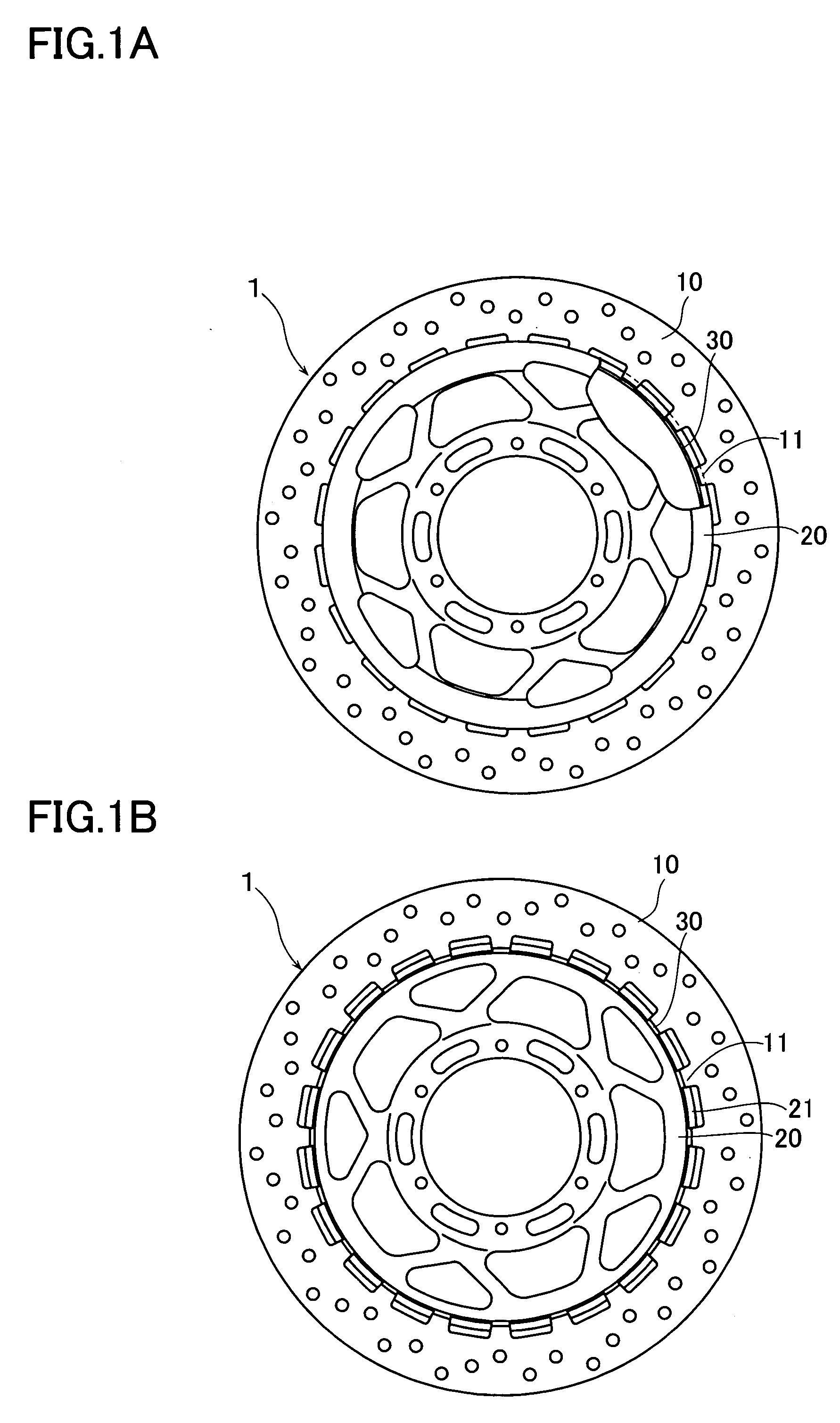
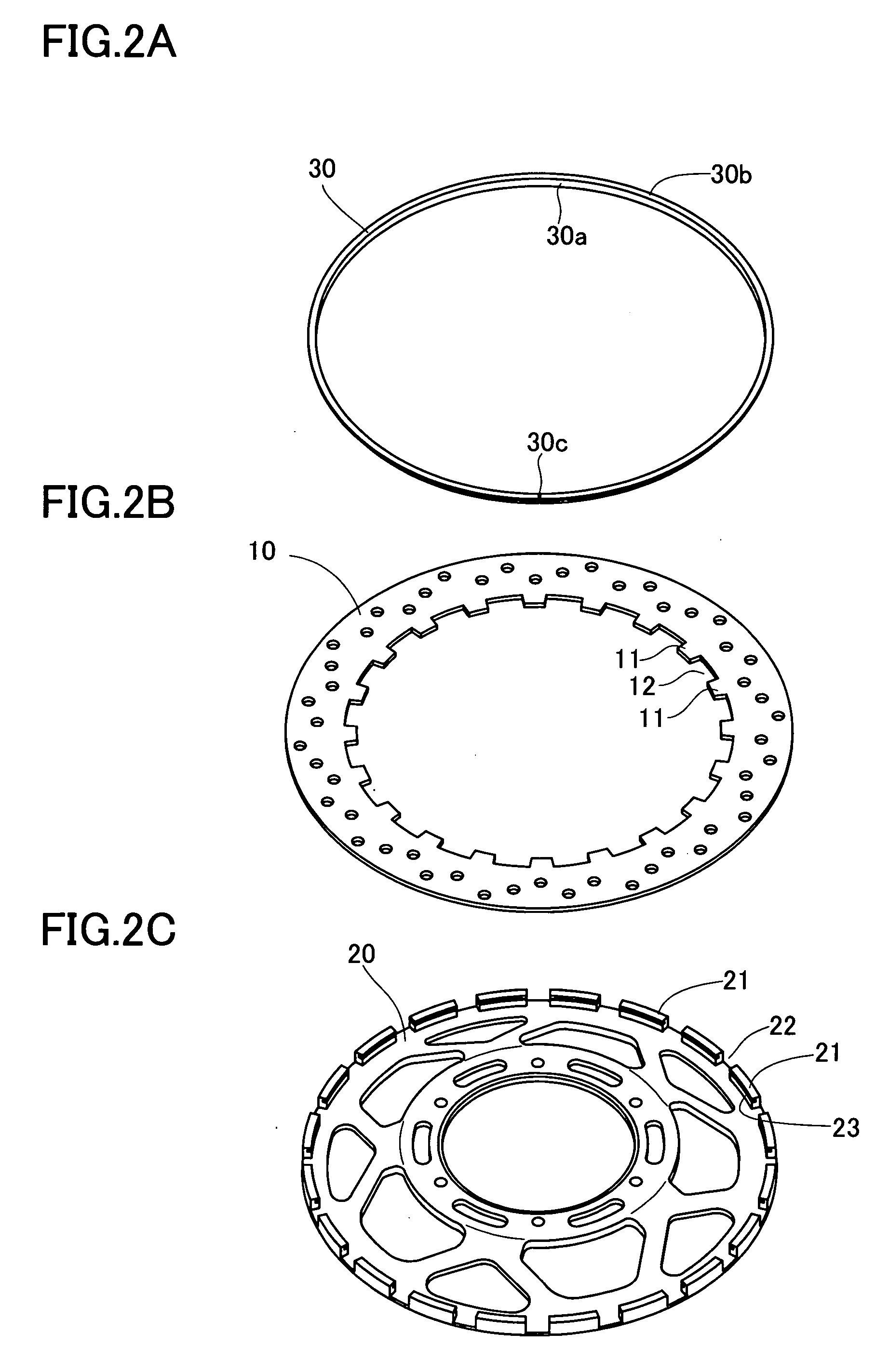
[0057]FIGS. 1A and 1B are views showing an embodiment of a floating type disc brake in accordance with the present invention, in which FIG. 1A is a front elevational view and FIG. 1B is a back elevational view. FIG. 2 is a perspective view of constituting parts of the brake disc as seen from a back surface side, FIG. 3 is a perspective view showing a part of the brake disc in a partly cutting manner from a front surface side, and FIG. 4 is a cross sectional view showing an assembling method of the brake disc.

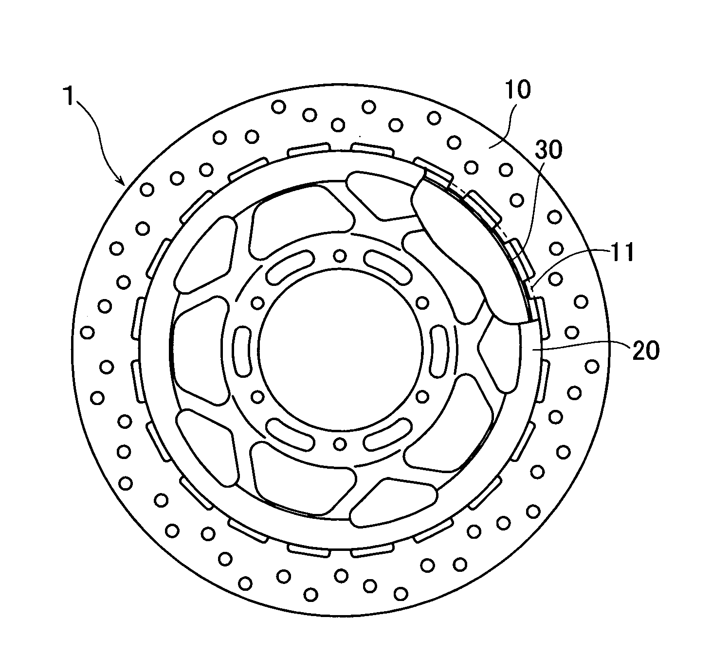
[0058] As shown in FIG. 1, a floating type brake disc 1 in accordance with the present embodiment is constituted by an annular rotor 10, a disc-like hub 20 and an annular ring spring 30.

[0059] The rotor 10 is provided, as shown in FIG. 2, with a lot of, for example, ten to twenty four, protruding portions 11 in a radial directi...

embodiment 2

[0078] In accordance with the present embodiment, there is shown an example in which a setting property of the ring spring is improved and an easiness of manufacturing is improved. A bending angle of the ring spring 30 having the approximately L-shaped cross section is made gentle to about 90 degree as shown in FIG. 9C. Further, a protrusion piece 35 having approximately the same width as a width of the protrusion portion 11 of the rotor 10 is formed so as to leave a space in the peripheral direction of one line 30a, by notching one line 30a in the axial direction of the ring spring 30 up to a portion near a boundary portion with another line 30b in the radial direction toward the peripheral direction. A projection 36 is provided in a protruding manner in the peripheral direction on an outer peripheral surface of the protrusion piece 35, by previously forming a groove 36a in the peripheral direction in a portion of an inner peripheral surface of the protrusion piece 35 on the basis ...

embodiment 3

[0084] The present embodiment shows an example employing the other spring than the ring spring having the approximately L-shaped cross section.

[0085] In the present embodiment, as shown in FIG. 10A, the ring spring 38 is constituted by a corrugated continuous integrally formed ring or a discontinuous open ring. The ring spring 38 is pressure contacted with the inner peripheral surface side of the protruding portion 11 by deflecting the ring spring 38 so as to be contracted, and bringing the ring spring 38 into contact with the inner peripheral surface of the protrusion portion 11 of the rotor 10 facing to the inner side in the radial direction from the gap 22 between the projection portions 21 of the hub 20. Further, a line (another line) 40b in a radial direction of a hold ring 40 constituted by an open ring having an L-shaped cross section is fitted to the groove 23 provided in the inner peripheral surface of the leading end portion in the projection portion 21 of the hub 20, the...


PUM


Abstract

The invention provides a floating type brake disc which can absorb a shock applied to a hub from a rotor at a time of running on a punishing road, can improve a heat lowering performance and can widely reduce a number of parts. A brake disc (1) is constituted by a hub (20), a rotor (10) and a ring spring (30). A lot of protrusion portions (11) in a radial direction are provided along a peripheral direction in an inner peripheral edge portion of the rotor (10), the same number of projection portions (21) in an axial direction are provided along the peripheral direction in an outer peripheral edge portion of the hub (20), and the protrusion portions (11) are protruded to an inner side in the radial direction through a gap (22) between the projection portions (21). The ring spring (30) is constituted by an open ring having an approximately L-shaped cross section. A line (30b) in a radial direction of the ring spring is fitted and mounted to a groove (23) in an inner peripheral surface of the projection portion (21) of the hub protruding from the rotor, and an inner peripheral surface of a protrusion portion (12) in the rotor is pressed to an outer side in the radial direction by a line (30a) in the axial direction of the ring spring.

Description

TECHNICAL FIELD [0001] The present invention relates to a floating type brake disc for a disc brake used for braking a vehicle, such as a motor cycle or the like. BACKGROUND ART [0002] A floating type brake disc is structured by connecting a disc-like aluminum hub, and an annular stainless steel rotor coaxially arranged in an outer side of the hub by an elastic member. [0003] A conventional floating type brake disc is provided with a hub “a” having semicircular recess portions “a1” in an outer peripheral edge portion leaving a space in a circumferential direction, and a rotor “b” having semicircular recess portions “b1” in an inner peripheral edge portion leaving a space in a circumferential direction, as shown in FIG. 21, and is prevented from coming off by butting the recess portion “a1” of the hub “a” to the recess portion “b1” of the rotor “b”, inserting a common pin “c” having a flange “c1a” in one end to a circular hole formed by the recess portions “a1” and “b1” via a washer ...

Claims


Application Information

Patent Timeline
IPC IPC(8): F16D65/12
CPCF16D65/12F16D2065/1316F16D2065/1396F16D2065/1368F16D2065/1392F16D2065/1348
Inventor YAMAMOTO, SHUSUKE
Owner YUTAKA GIKEN CO LTD
Why Eureka
Try Eureka