Circuit for extracorporeal blood treatment and flow-inverting device utilized therein

a flow-inverting device and extracorporeal blood technology, applied in the direction of moving filter element filters, filtration separation, separation processes, etc., can solve the problems of reducing the performance of vascular access, affecting the reliability of measurement, and affecting the patient's treatment efficiency, so as to achieve optimal counter-current conditions

Inactive Publication Date: 2005-07-07
GAMBRO LUNDIA AB
View PDF2 Cites 15 Cited by
  • Summary
  • Abstract
  • Description
  • Claims
  • Application Information

AI Technical Summary

Benefits of technology

[0029] It is a secondary aim of the invention to provide a circuit for extracorporeal blood treatment in which a flow inversion can be obtained at the vascular accesses to the patient by an inversion of the thrust exerted by the blood pump and that is also capable of maintaining optimal counter-current conditions within the blood treatment unit.
[0030] It is a further aim of the invention to provide a circuit and a device for flow inversion capable of automatically maintaining the blood flow within the filtering unit constant even following inversion of the flow at the vascular accesses to the patient.
[0031] It is then an auxiliary aim of the invention to provide a device for flow inversion of different structure and conception as compared with the devices hitherto on the market, which is cheap and very reliable.

Problems solved by technology

It is therefore apparent that a decrease in the performance of the vascular access may represent a serious problem for the patient and therefore the vascular access must be periodically monitored to ensure an optimal functional character of same.
It is in fact apparent that, if due to a degradation of the arteriovenous aneurysm for example (that may be due to the most different causes such as formation of stenosis, collapsing of the vascular walls or others), there is a decrease in the blood flow therein, the dialysis machine will be able to draw a lower amount of blood which will bring about a worsening in the treatment efficiency.
It is apparent that carrying out this operation manually, i.e. by slipping the respective needles off and inverting suction with delivery in the patient, involves a great trouble for the patient, is time-consuming and as a matter of fact undermines reliability of the measurement of these parameters that are also partly linked to quickness in the inversion.
The two discs have appropriate fluid accesses, those of one disc being susceptible of connection with the blood lines directly associated with the patient and those of the other disc being susceptible of direct connection with the bloodlines in fluid communication with the filtering unit.
However this device is not used to invert the circulation flow at the vascular accesses to the patient, but to enable flow inversion within the filtering unit.
All the patented devices briefly mentioned above however appeared to be susceptible of improvements under different points of view.

Method used


Image

  • Circuit for extracorporeal blood treatment and flow-inverting device utilized therein
  • Circuit for extracorporeal blood treatment and flow-inverting device utilized therein
  • Circuit for extracorporeal blood treatment and flow-inverting device utilized therein

Examples


first embodiment

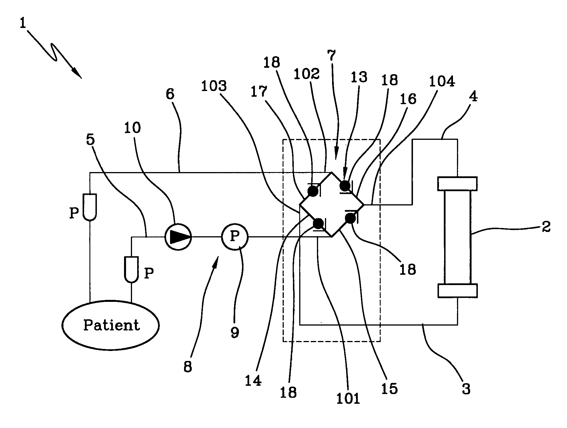
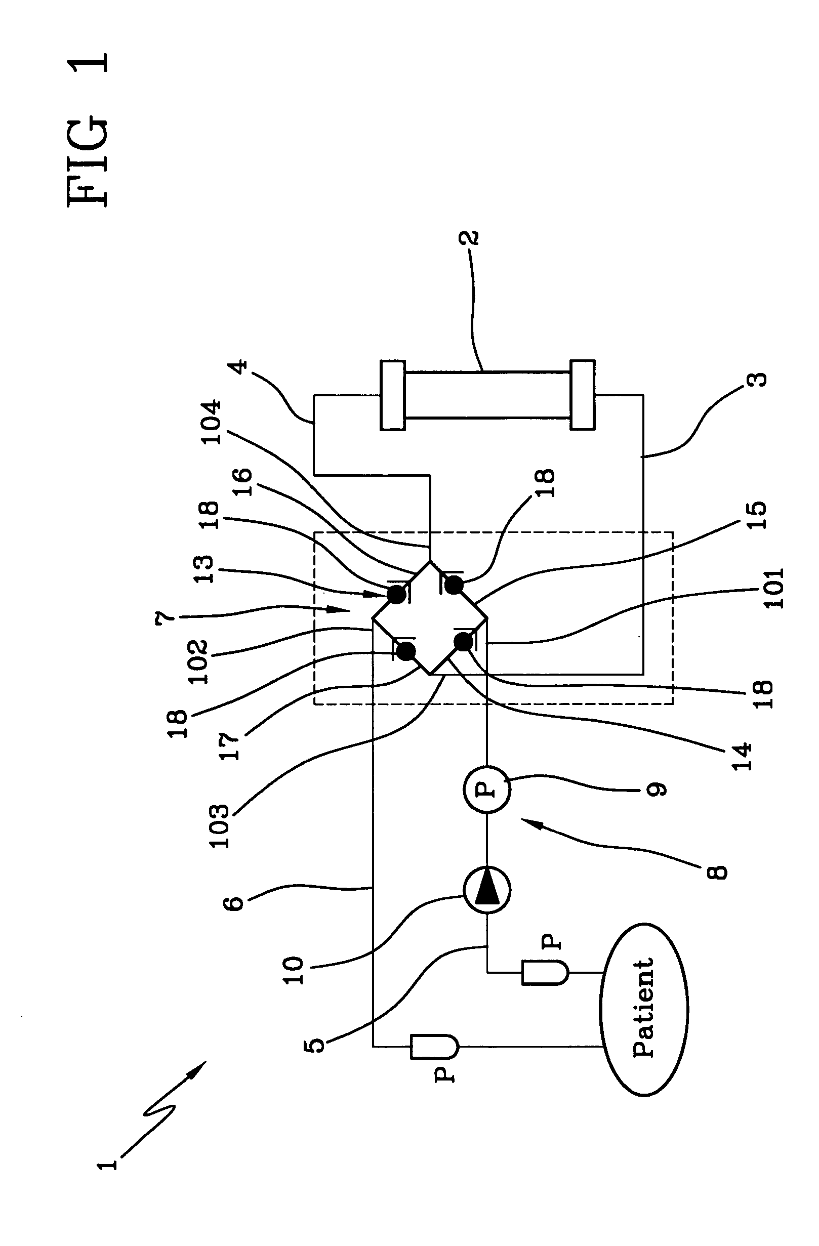
[0052] In the first embodiment, each of said accesses is connected by appropriate connecting lines 14, 15, 16, 17 to at least two other accesses of the device.

[0053] As viewed from the accompanying FIGS. 1-3, the first connecting line 14 brings the first access 101 into fluid communication with the third access 103, the second connecting line 15 brings the first access 101 into fluid communication with the fourth access 104, the third connecting line 16 brings the second access 102 into fluid communication with the fourth access 104, whereas the fourth connecting line 17 brings the second access 102 into fluid communication with the third access 103.

[0054] In other words and as better clarified in the following when operation of the circuit is explained, the first access 101 can be selectively brought into communication with either the third access 103 or the fourth access 104, whereas the second access 102 can be selectively brought into fluid communication with either the fourth ...

second embodiment

[0061] Obviously for the above purpose can be also taken into consideration members provided with spring-return elements capable of enabling blood passage in one direction alone and only in the presence of overpressures (this is true also with respect to the second embodiment).

[0062] After the above statements from a structural point of view, operation of the circuit for extracorporeal blood treatment (first embodiment) is the following.

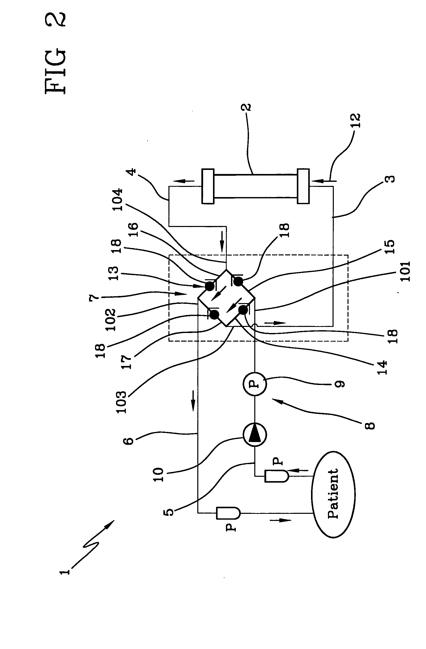
[0063] In a first work condition of the movement means 8, the peristaltic pump 9 generates a direct flow (arrow 10 in FIG. 2) in which the blood is drawn from the patient's vascular access through the patient-side artery branch 5 and is then moved towards the flow-inverting device 7 reaching the first access 101.

[0064] Under this situation the flow pressure is of such a nature that opening of the check valve 18 connected to the first connecting line 14 is allowed thereby causing blood passage to the third access 103.

[0065] Simultaneously, the chec...

third embodiment

[0100] Both the second and the flow-inverting device 7 show a blood flow coming from the filter 2 through the unit-side vein branch 4 which is directed, in the first work condition of the movement means 8, towards the second access 102, while it is directed, in the second work condition of the movement means, towards the first access 101.

[0101] In other words the thrust inversion of the peristaltic pump 9 does not affect the blood flow in the fourth access 104 while it inverts blood flow in the first and second accesses 101, 102.

[0102] In other words the second portion 7b comprises means 57 for allowing, in the first work condition, a blood flow from the first access 101 to the main outlet 54 and from the fourth access 104 towards the second access 102 and for allowing, in the second work condition, a blood flow from the second access 102 to the auxiliary outlet 55 and from the fourth access 104 towards the first access 101.

[0103] In the second embodiment said means 57 comprises a...


PUM

PropertyMeasurementUnit
movementaaaaaaaaaa
degree of freedomaaaaaaaaaa
flow pressureaaaaaaaaaa

Abstract

It is disclosed a circuit for extracorporeal blood treatment in which a flow-inverting device is interposed between a blood treatment unit and a blood pump placed on an artery branch connected with a vascular access of a patient. The flow-inverting device allows the blood flow within the filtering unit to be kept unchanged even following an inverted circulation in the patient-side artery and vein branches controlled by the blood pump.

Description

FIELD AND BACKGROUND OF THE INVENTION [0001] The present invention relates to a circuit for extracorporeal blood treatment and the relevant device for flow inversion utilised therein. [0002] It is known that during extracorporeal blood treatment the patient's vascular system is connected to a machine or unit for blood treatment, a dialysis machine, for example. [0003] Connection to the machine creates a circuit in which the blood is drawn from the patient through a needle or other vascular access device connected to the patient itself; the blood is caused to circulate through the unit operating the appropriate treatments on the blood and is then returned to the patient through a return line and a corresponding needle or other access also connected to the patient's vascular system. [0004] The interface between the machine and patient is made up of the vascular access from which the blood to be treated is drawn and to which the treated blood is caused to come back to the human body. I...

Claims


Application Information

Patent Timeline
Patent Type & Authority Applications(United States)
IPC IPC(8): A61M1/36A61M39/22
CPCA61M1/367A61M1/3658A61M39/223Y10T137/87249A61M1/362265
Inventor JONSSON, LENNARTHOLMER, MATTIASHANSSON, PER
Owner GAMBRO LUNDIA AB
Why Eureka
Try Eureka