
Container cleaning device

Inactive Publication Date: 2005-07-07
VITA MIX MANAGEMENT
View PDF13 Cites 29 Cited by
  • Summary
  • Abstract
  • Description
  • Claims
  • Application Information

AI Technical Summary

Benefits of technology

[0007] It is thus an object of the present invention to provide a device which can reliably be used to clean a wide variety of food and beverage containers.
[0009] It is a further object of the present invention to provide a device, as above, which will satisfactorily operate at low pressure water conditions.
[0010] It is an additional object of the present invention to provide a device, as above, which can be quickly and easily attached to, and detached from, a water source such as a faucet.
[0011] It is yet another object of the present invention to provide a device, as above, which will not leak when it is detached from a faucet.

Problems solved by technology

Many liquid food containers, such as pitchers and the like, are difficult to clean, primarily because of their depth.
Moreover, these types of containers are often in need of frequent cleaning, for example, in commercial environments, such as a restaurant or cocktail lounge, where the pitcher component of a blender may be continually used to blend different drinks.
However, such a device does not assure the complete cleaning of the entire container, particularly those that are quite deep.
Moreover, the low profile unit is particularly ineffective for cleaning the bottom of a container, and when the container bottom includes blades, as would be found in a container of a blender, the bottom of the blades are particularly difficult to clean.
A problem with this type of device, however, relates to the seal that must be provided at the top of the tower, which problem is compounded in low pressure water conditions.
There was a large amount of surface contact which, therefore, required a relatively high amount of force to maintain the seal.
As a result, low water pressure conditions might well cause leakage.

Method used


Image

  • Container cleaning device
  • Container cleaning device
  • Container cleaning device

Examples


Embodiment Construction

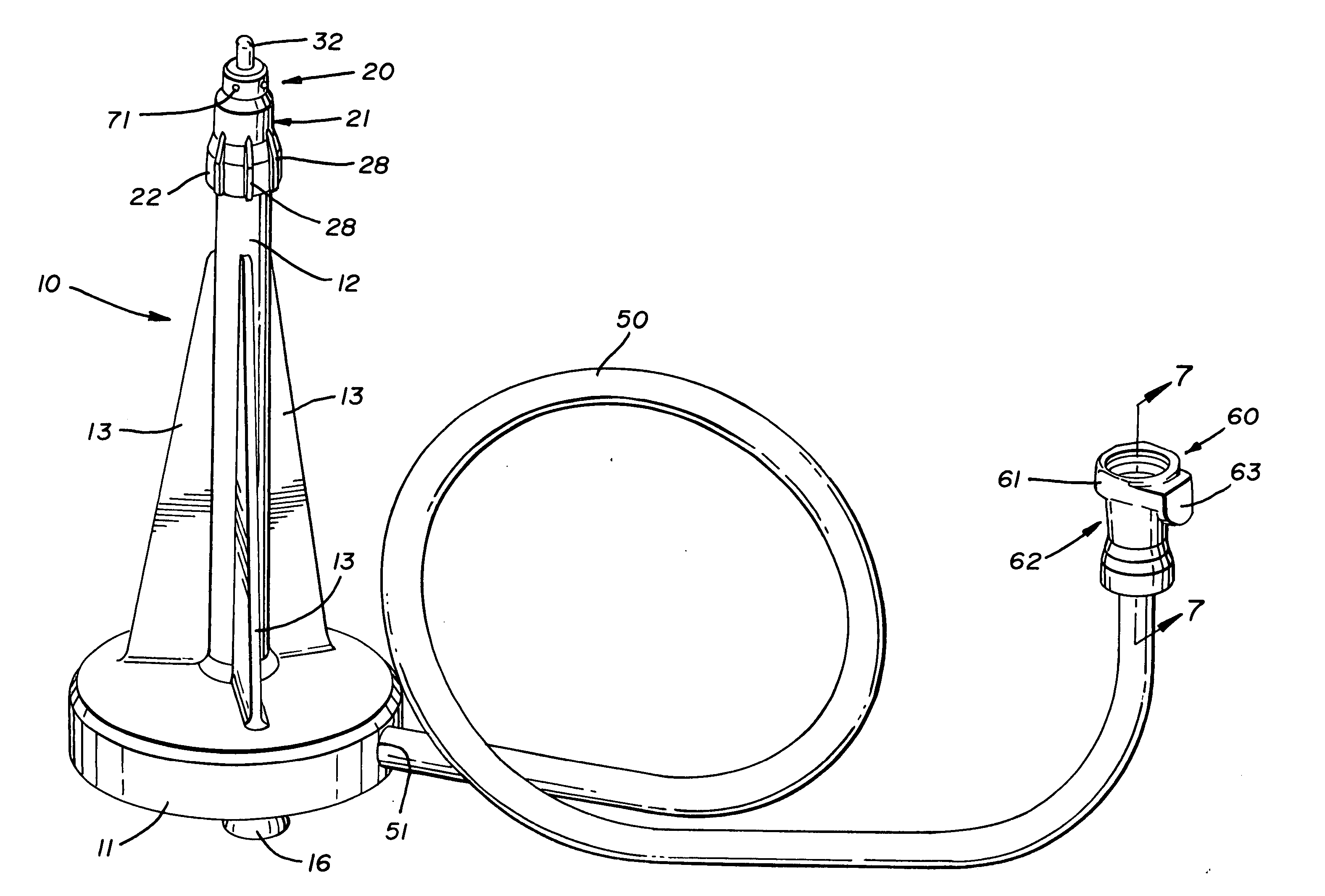
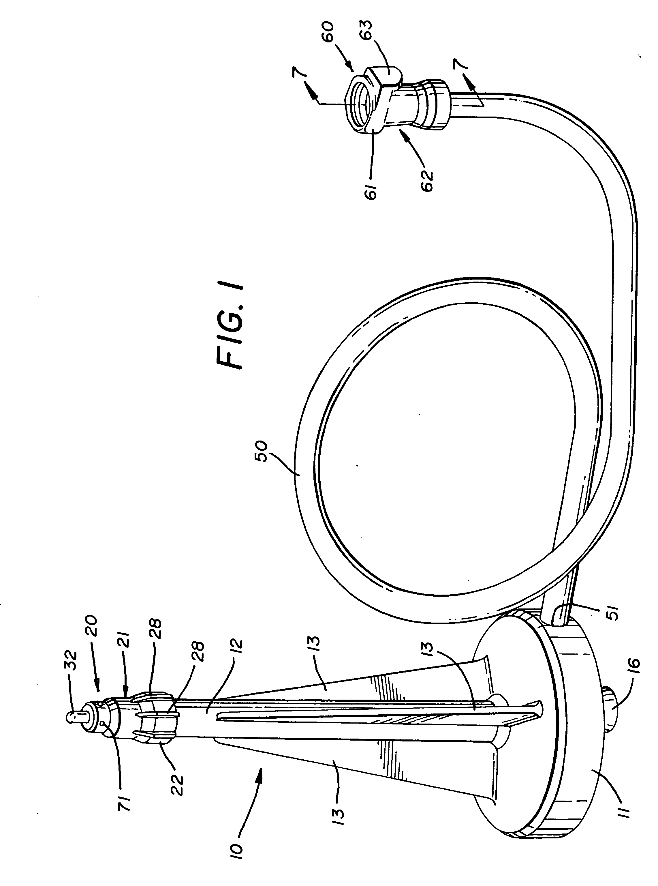
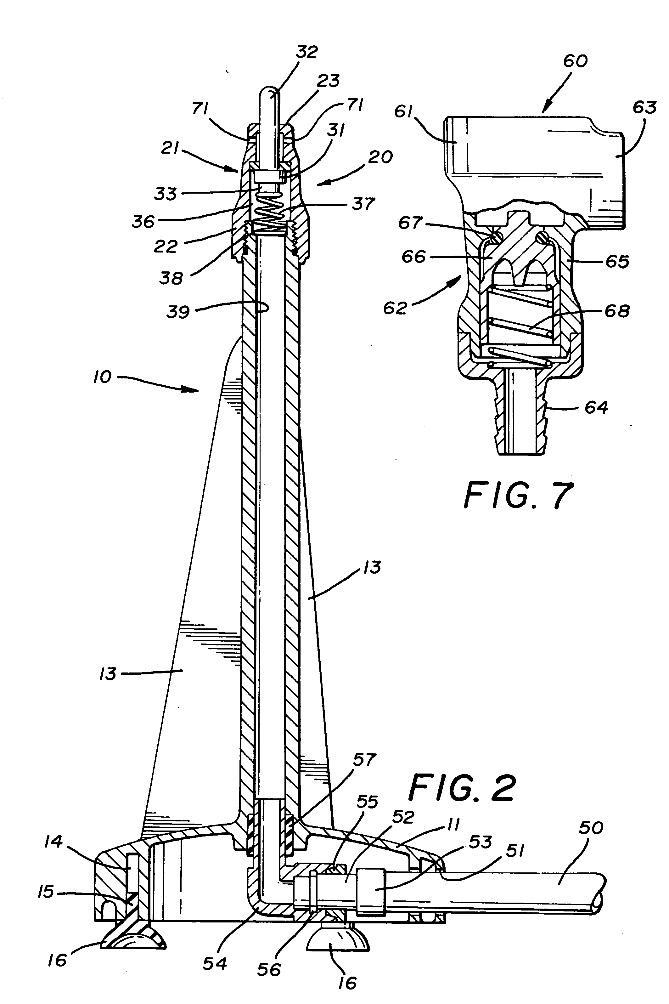
[0026] A device for cleaning the inside of a container is indicated generally by the numeral 10, the majority of the components thereof preferably being molded of a suitable plastic material such as acrylonitrile butadiene styrene (ABS) or similar material. Device 10 includes a generally cylindrical plastic base 11 which preferably integrally carries an upstanding plastic tube 12 which is open at its bottom into base 11. A plurality of tapered fins 13 may be provided between the outer wall of tube 12 and base 11 to provide strength to tube 12. Base 11 may be provided with a plurality of slots 14, one being shown in FIG. 2, each of which receives a stem 15 of a suction cup-like foot 16. Feet 16 thus enable device 10 to be securely positioned on a surface, usually a sink or other surface communicating with a fluid drain.

[0027] A nozzle assembly, generally indicated by the numeral 20, is carried at the top of tube 12. Nozzle assembly 20 includes a plastic spray head generally indicate...


PUM


Abstract

A device (10) for cleaning the inside of a container includes a base (11) carrying a tube (12). A hose (50) is received within the base (11) and is connected at one end to the bottom of the tube (12) and at the other end to a source of water via a quick disconnect assembly (60). A spray head (21) houses a plunger (30) which has a base (31) and a nose (32). A spring (37) urges the nose (32) of the plunger (30) out through an aperture (40) in the spray head (21). A flat washer seal (42) is positioned with a majority of its surface on a shelf (41) formed in the spray head (21). Ribs (43) on the shelf (41) engage the seal (42) on one side, and a rim (44) on the base (31) engages the other side of the seal (42). The quick disconnect assembly (60) includes a valve (66) which is maintained closed by a spring (67) so that when the hose (50) is disconnected from the source of water, or the water supply pressure is lost, backflow is prevented. When a container is inverted and its bottom pushed down on the top of the nose (32) of the plunger (30), the base (31) of the plunger (30) is moved away from the seal (42) to allow water to be emitted from spray head (21) through axial apertures (70) and radial apertures (71).

Description

TECHNICAL FIELD [0001] This invention relates to a device for cleaning a container. More particularly, this invention relates to a device which can emit a high pressure spray to clean the inside of a liquid food container such as a pitcher or the like. BACKGROUND ART [0002] Many liquid food containers, such as pitchers and the like, are difficult to clean, primarily because of their depth. Moreover, these types of containers are often in need of frequent cleaning, for example, in commercial environments, such as a restaurant or cocktail lounge, where the pitcher component of a blender may be continually used to blend different drinks. [0003] One possible way to clean these deep containers is to provide a nozzle-like device at the end of a hose. Such, however, requires the close attention of the user who must hold the container with one hand and the nozzle with the other while directing the spray to various locations in the container. [0004] In an alternative solution to the problem,...

Claims


Application Information

Patent Timeline
IPC IPC(8): A47L15/00B05B1/14B05B1/30B05B15/06B08B9/08
CPCA47L15/0065A47L15/4278B05B1/14B08B9/0826B05B1/304B05B15/061B05B1/3006B05B15/62
Inventor KATZ, JONATHAN M.RUKAVINA, STEPHEN P.BOOZER, RICHARD D.
Owner VITA MIX MANAGEMENT
Learn More