Resonant scanning mirror with inertially coupled activation

Inactive Publication Date: 2005-07-07
TEXAS INSTR INC
View PDF2 Cites 68 Cited by
  • Summary
  • Abstract
  • Description
  • Claims
  • Application Information

AI Technical Summary

Problems solved by technology

Unfortunately, these prior art efforts of using a scanning or oscillating mirror have required a compromise in performance in that only one direction of the resonant beam sweep could be used to print an image line at a right angle on a page.
Unfortunately, if the mirror is mounted at a slight angle to compensate for medium movement during the forward beam sweep, the return beam sweeps will traverse a trajectory on the moving photosensitive drum which will be at an angle which is unacc

Method used


Image

  • Resonant scanning mirror with inertially coupled activation
  • Resonant scanning mirror with inertially coupled activation
  • Resonant scanning mirror with inertially coupled activation

Examples


Embodiment Construction

[0031] The making and using of the presently preferred embodiments are discussed in detail below. It should be appreciated, however, that the present invention provides many applicable inventive concepts that can be embodied in a wide variety of specific contexts. The specific embodiments discussed are merely illustrative of specific ways to make and use the invention, and do not limit the scope of the invention.

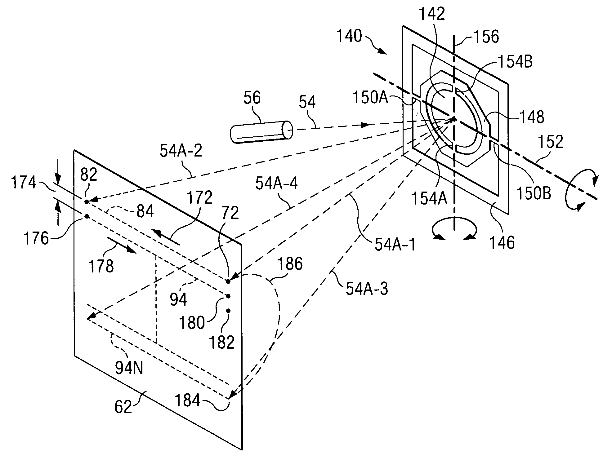
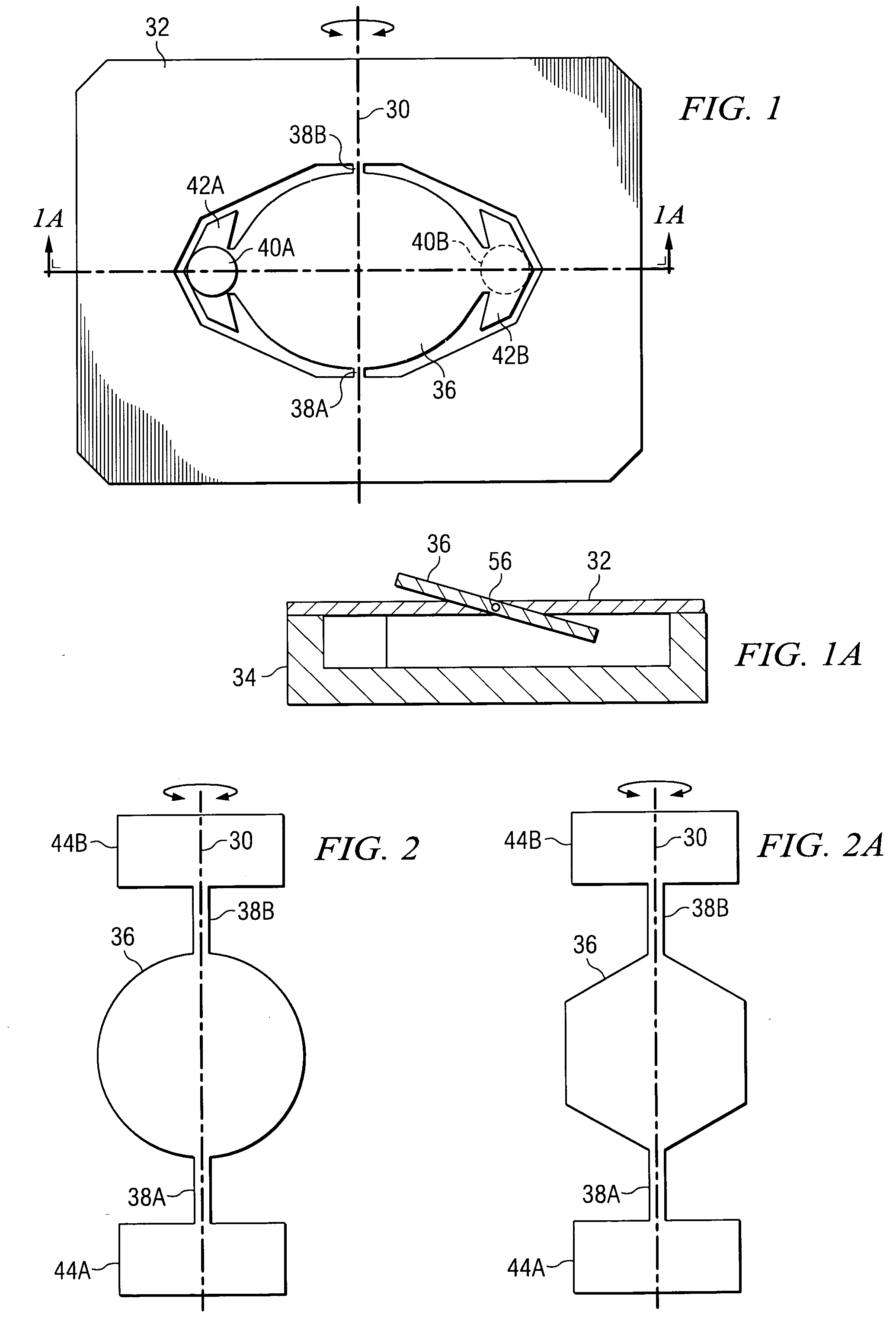
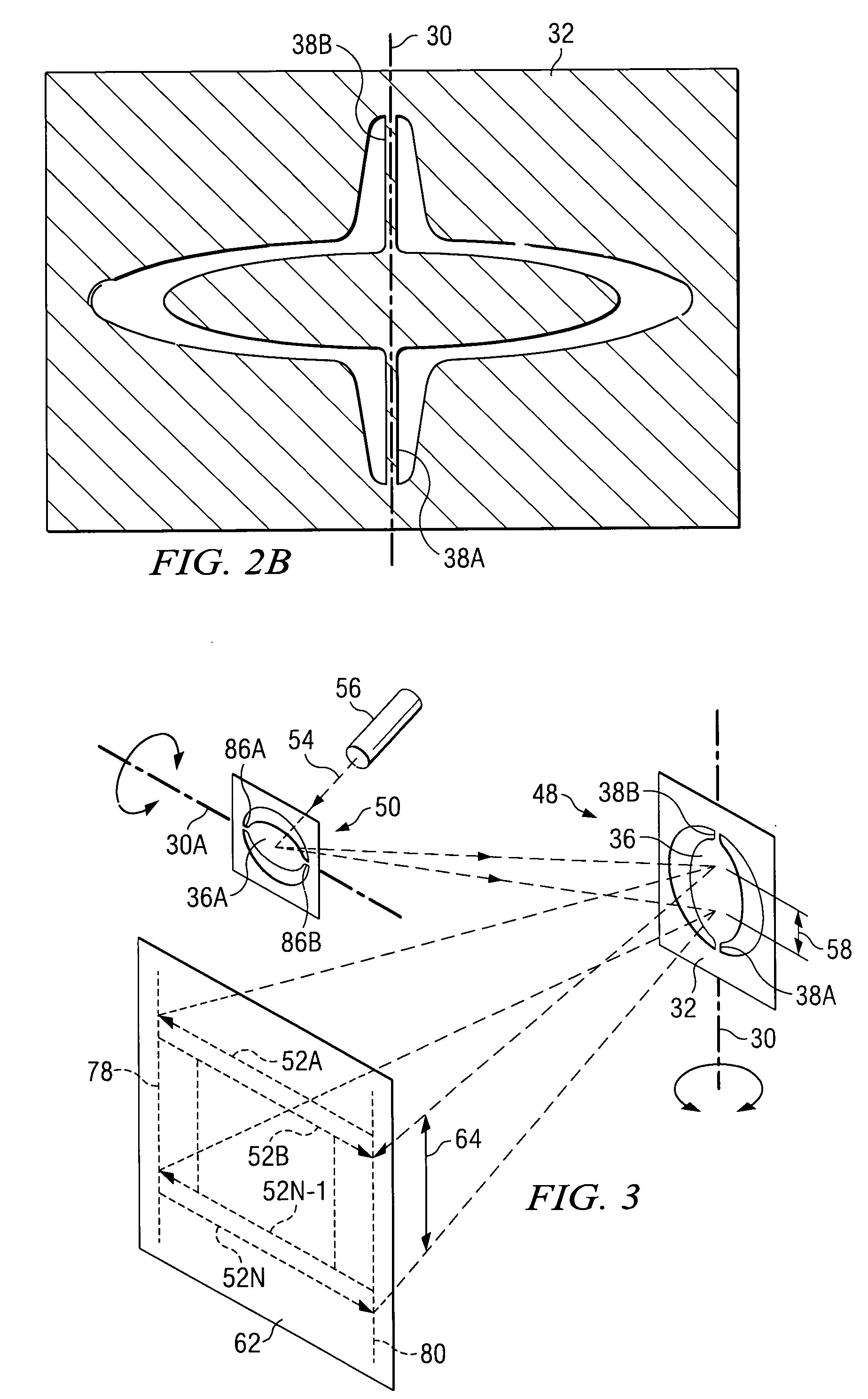
[0032] Like reference numbers in the figures are used herein to designate like elements throughout the various views of the present invention. The figures are not intended to be drawn to scale and in some instances, for illustrative purposes, the drawings may intentionally not be to scale. One of ordinary skill in the art will appreciate the many possible applications and variations of the present invention based on the following examples of possible embodiments of the present invention. The present invention relates to mirror apparatus with a moveable reflecting surface th...


PUM


Abstract

A system and method for providing a resonant beam sweep about a first axis. A mirror or reflective surface supported by a first pair of torsional hinges is driven into resonant oscillations about the first axis by inertially coupling energy through the first pair of torsional hinges. A light source reflects a beam of light from the mirror such that the oscillating mirror produces a beam sweep across a target area. The resonant beam sweep is moved orthogonally on the target area by a gimbals portion of the mirror pivoting about a second axis according to one embodiment. A second independent mirror provides the orthogonal movement according to a second embodiment.

Description

[0001] This application claims the benefit of U.S. Provisional Application No. 60 / 394,321, filed on Jul. 8, 2002, entitled Scanning Mirror, which application is hereby incorporated herein by reference.TECHNICAL FIELD [0002] The present invention relates generally to projection displays and laser copiers. More specifically, the invention relates to the use of MEMS (micro-electric mechanical systems) type mirrors (such as torsional hinge mirrors) to provide resonant scanning of a light beam on a display screen or on a photosensitive medium. The resonant scan may be generated by using a single dual axis mirror or two single axis mirrors. A first set of torsional hinges is used for providing the resonant scan by oscillating the mirror about the torsional hinges at the mirror's resonant frequency if a dual axis mirror is used. Alternately, a first one of two single axis mirrors may be driven to resonance about its torsional hinges to provide the bi-directional scan. The second pair of to...

Claims


Application Information

Patent Timeline
IPC IPC(8): G02B7/182G02B26/08
CPCG02B7/1821G02B26/0833G02B26/0858G02B26/085G02B26/0841G02B26/101
Inventor TURNER, ARTHUR MONROEDEWA, ANDREW S.HEATON, MARK W.
Owner TEXAS INSTR INC
Why Eureka
Try Eureka