Variable sprocket ivt machine

Inactive Publication Date: 2005-07-07
VARIBOX IP
View PDF6 Cites 24 Cited by
  • Summary
  • Abstract
  • Description
  • Claims
  • Application Information

AI Technical Summary

Benefits of technology

[0016] The control arrangement may comprise a controller for moving the arcuate element towards and away from the machine input shaft and means for concomitant

Problems solved by technology

Another problem with these prior art machines is the non-exact synchronisation of their engagement devices with the flexible member (chain) links where engagement is accomplished via spring loaded sprocket teeth or rotatable

Method used


Image

  • Variable sprocket ivt machine
  • Variable sprocket ivt machine
  • Variable sprocket ivt machine

Examples


Embodiment Construction

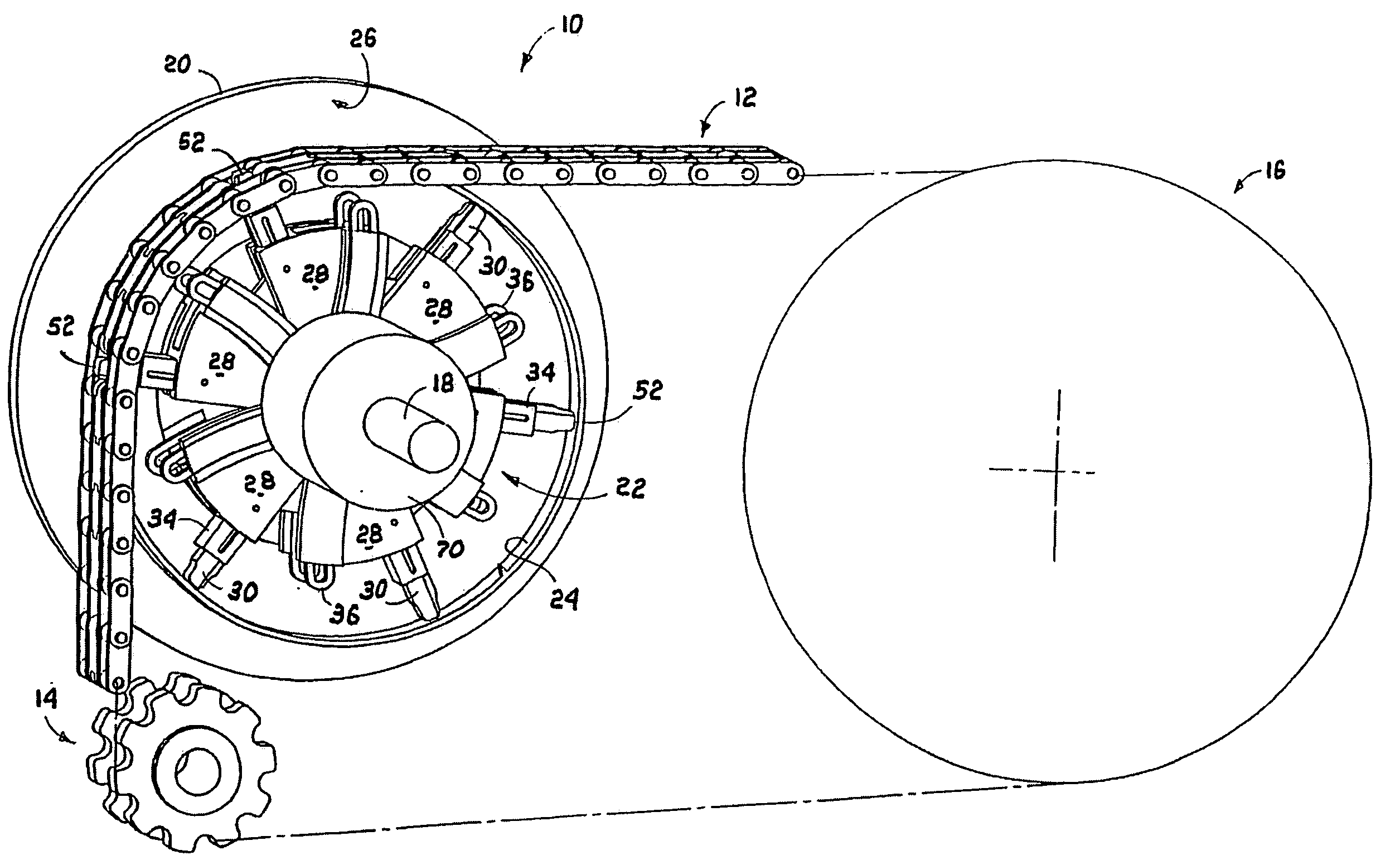
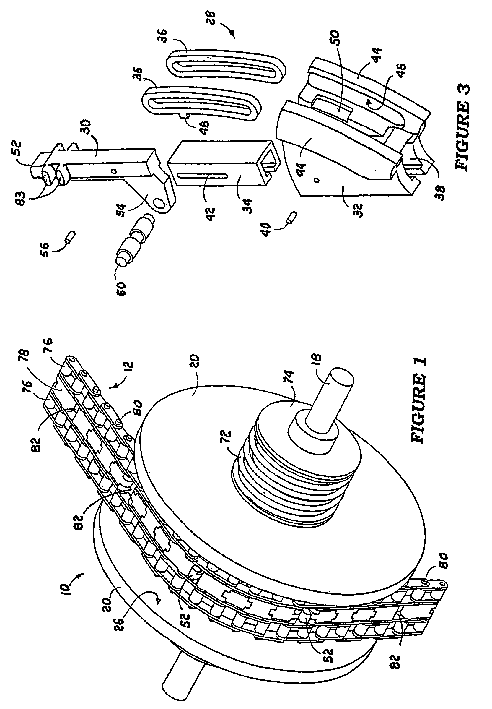
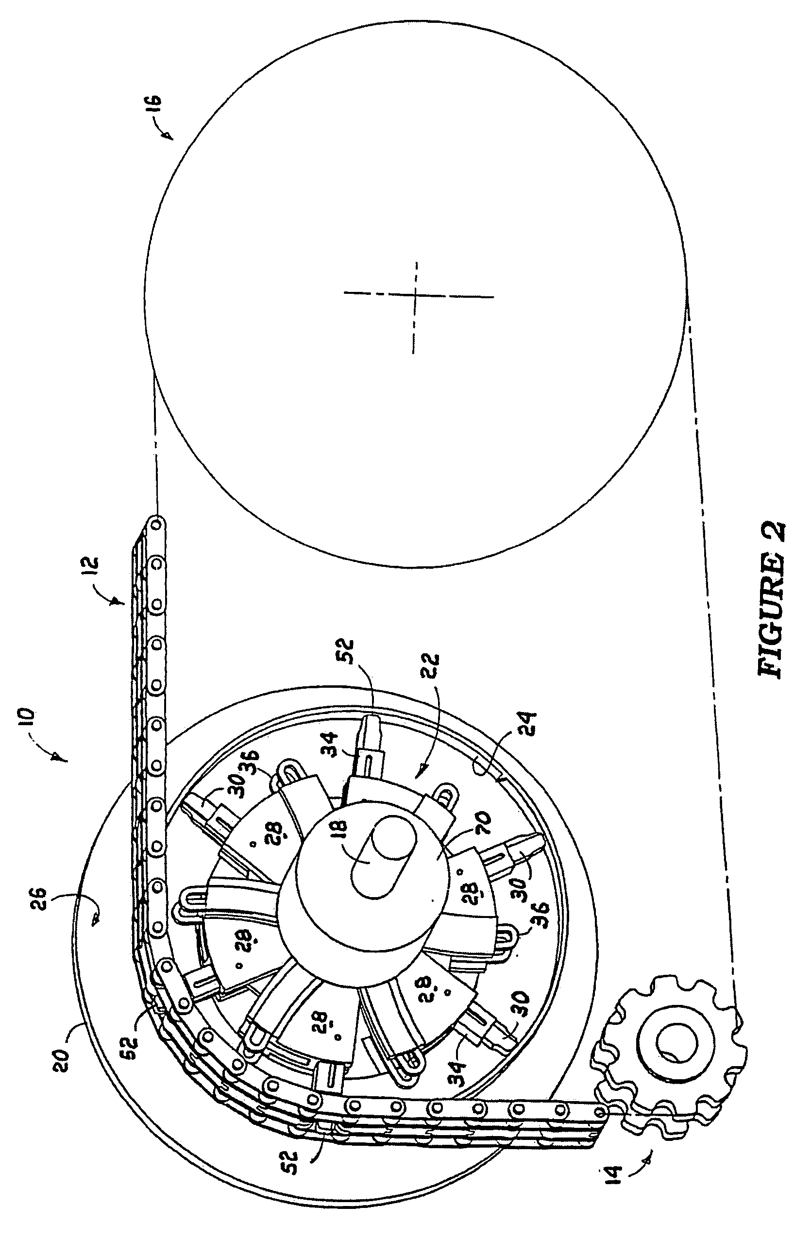
[0029] The IVT machine of the invention is shown in FIGS. 1 and 2 to include a variable diameter sprocket wheel assembly 10, an endless drive chain 12, a pair of chain positioning sprockets 14 and whatever is to be driven 16 by the chain 12.

[0030] The sprocket wheel assembly 10 of FIGS. 1 and 2 is shown mounted on a machine input shaft 18 and includes two opposed chain guide discs 20, a variable diameter sprocket wheel 22 and an arcuate control element 24.

[0031] The chain guide discs 20 each have flat outer faces and inner face portions 26 which taper outwardly from a central zone of the disc to its periphery as shown only diagrammatically in FIG. 7 and clearly in FIG. 6. The mounting of the discs 20 in the machine will be described below.

[0032] The sprocket wheel 22, in this embodiment of the invention, is a composite wheel which includes six identical wheel bodies 28 which each carry an elongated chain engaging sprocket 30.

[0033] The wheel bodies 28 each include, as shown in F...


PUM


Abstract

A variable sprocket IVT machine has a sprocket wheel, on an input shaft, including a plurality of wheel bodies which are independently rotatable on the shaft, a sprocket slidably located in and projecting radially from a sleeve in each wheel body, connecting arrangements, connecting the wheel bodies in the composite wheel, which are adapted to vary the angular disposition between and the degree of radial projection of adjacent sprockets relatively to each other to ensure clean engagement of the sprockets with uniformly spaced apertures in a drive chain which partially surrounds the wheel in a radially movable zone of sprocket engagement, elements for engaging the wheel bodies of the sprockets in the zone with the input shaft and a control arrangement which supports the sprockets not in the zone and which is movable to vary the ratio of rotation of the input shaft relatively to a chain driven output shaft.

Description

FIELD OF THE INVENTION [0001] This invention relates to an infinitely variable transmission (IVT) machine in which the ratio of rotation between the input and output shafts of the machine is steplessly infinitely variable by means of a sprocket wheel which is variable in diameter. BACKGROUND TO THE INVENTION [0002] A significant body of prior art relating to IVT machines of the above type exists. Typical examples of these are described in the following publications: U.S. Pat. No. 4,878,883, GB2062142A, GB2135743A, U.S. Pat. Nos. 4,618,331, 3,956,944 and 5,984,814. [0003] It will be seen from the specifications of U.S. Pat. Nos. 4,618,331 and 3,956,944 that these machines largely consist of radially positionable engagement devices that operate, either by means of sprocket teeth or frictionally, within fixed tracks which are spaced radially about the variable sprocket hub. Because of the limited number of engagement devices the flexible member track around them does not constitute a c...

Claims


Application Information

Patent Timeline
IPC IPC(8): B62M9/08F16G13/02F16H9/24F16H55/54
CPCB62M9/08F16G13/02F16H9/10F16H9/24F16H55/54
Inventor NAUDE, JOHANNES
Owner VARIBOX IP
Why Eureka
Try Eureka