Intervertebral body fusion cage with keels and implantation methods

a technology of intervertebral body and fusion cage, which is applied in the field of intervertebral body fusion cage, can solve the problems of ossification, thin, herniation, and occlusion of the intervertebral disk, and the common cause of intervertebral disk damage,

Active Publication Date: 2005-07-07
KYPHON
View PDF99 Cites 231 Cited by
  • Summary
  • Abstract
  • Description
  • Claims
  • Application Information

AI Technical Summary

Problems solved by technology

In addition to spinal stenosis and facet joint degeneration, the incidence of damage to the intervertebral disks is also common.
At birth, the disk is 80% water, but the water content gradually diminishes with time, causing the disk to stiffen.
With age, disks may degenerate and bulge, thin, herniate, or ossify.
Damage to disks also may occur as a result of disease, trauma, or injury to the spine.
Disk damage can have far-reaching consequences.
Loss of normal curvature effectively shortens the spinal canal, and decreases its capacity.
Fu

Method used


Image

  • Intervertebral body fusion cage with keels and implantation methods
  • Intervertebral body fusion cage with keels and implantation methods
  • Intervertebral body fusion cage with keels and implantation methods

Examples


embodiment 100

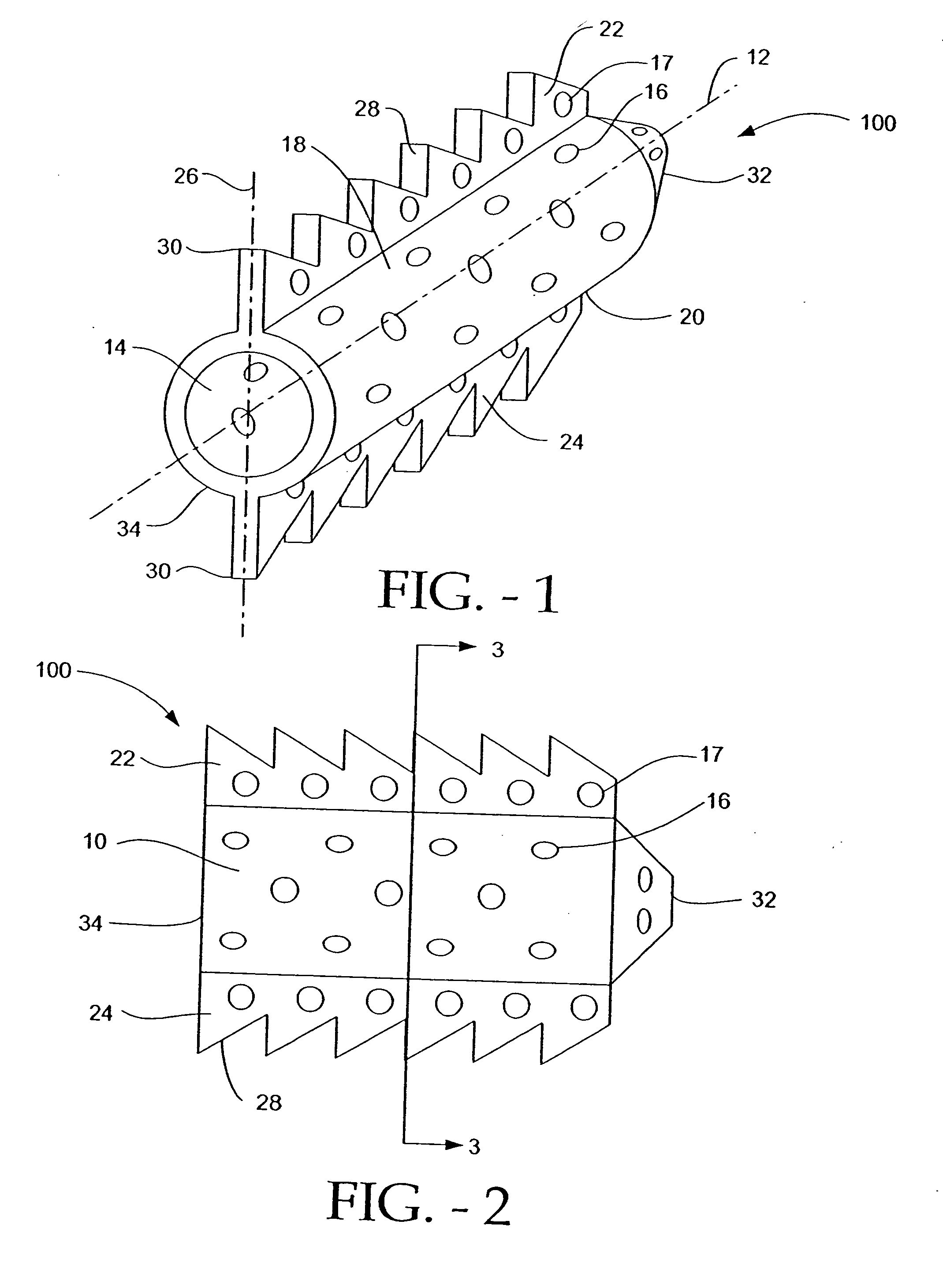
[0051] The cylindrical cage 10 has a superior surface 18 that abuts the upper vertebra of the two affected vertebrae, and an inferior surface 20 that abuts the lower vertebra. In this embodiment 100, a first keel 22, preferably substantially perpendicular to the sagittal plane of the body, extends along the longitudinal axis 12 of the cylindrical cage 10, and into the cancellous bone of the vertebral body of the top vertebra through a keel-receiving channel cut into the vertebral body of the top vertebra. Similarly, a second keel 24, preferably substantially perpendicular to the sagittal plane of the body, extends along the longitudinal axis 12 of the cylindrical cage 10, and into the cancellous bone of the vertebral body of the bottom vertebra through a keel-receiving channel cut into the vertebral body of the bottom vertebra. The keels include apertures 17 that allow the patient's vertebral bone to grow through to further stabilize and integrate the implant 100 into the upper and ...

embodiment 200

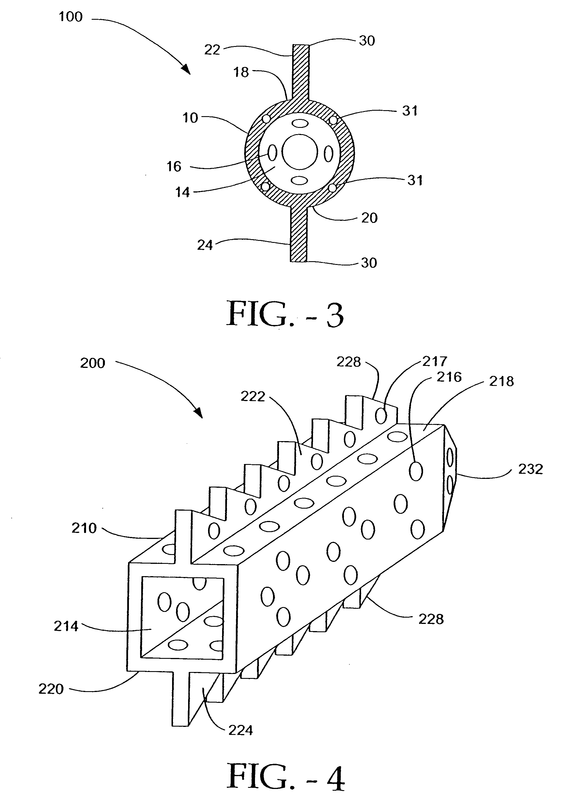
[0063]FIGS. 4-6 depict an embodiment 200 of the disclosed implant having a cage 210 with a cubical configuration. The cubical configuration can enhance the communication of the bone graft and bone growth-promoting contents contained in the hollow interior 214 of the cubical cage 210 by bringing a greater surface area of the cage 210, and hence, a greater amount of bone graft material, into direct contact with the cancellous bone of the vertebral bodies. Further the flat superior 218 and inferior 220 planar surfaces of the cage 210 create stabilizing surfaces that mate with the upper and lower end plates of the upper and lower vertebrae. It is to be understood that, for all embodiments, the vertebrae may be somewhat shaped in order to accept the superior 218 and inferior 220 planar surfaces of the cage 210.

[0064] As with the embodiments previously described, a plurality of keels 222, 224 is contemplated, extending from the superior 218 and inferior 220 surfaces of the cage 210 of the...

embodiment 400

[0071] It should be appreciated that embodiment 400 also can be implanted from an anterior or posterior approach. Either of those approaches would correct lateral curvature of the spine.

[0072]FIGS. 11-13 depict a further embodiment 500 of the disclosed implant. This embodiment 500 is similar to the embodiment 400 in FIGS. 8-10, with the difference being that the narrowest 538 and widest 540 surfaces of embodiment 500 are arranged opposite to their respective positions in embodiment 400. Like embodiment 400, embodiment 500 can be implanted laterally to restore normal curvature to the spine; alternatively, if implanted from an anterior or posterior approach, embodiment 500 would correct lateral curvature of the spine.

[0073] As discussed above, scoliosis, or abnormal lateral curvature of the spine, can also be corrected by positioning a wedge-shaped implant with keels in the intervertebral space. The implant can be constructed for different angles of correction, as with the implant fo...


PUM


Abstract

An intervertebral implant has a fusion body with at least one keel that anchors the implant into cancellous bone of at least one vertebral body. A method for implantation includes lateral implantation of the implant.

Description

CLAIM OF PRIORITY [0001] U.S. Provisional Patent Application No. 60 / 537,382 entitled INTEVERTEBRAL BODY FUSION CAGE WITH KEELS AND LATERAL IMPLANTATION METHOD, by Zucherman et al., filed Jan. 16, 2004 (Attorney Docket KLYCF-07001US0); [0002] U.S. Provisional Patent Application No. 60 / 523,604 entitled INTEVERTEBRAL BODY FUSION CAGE WITH KEELS AND LATERAL IMPLANTATION METHOD, by Zucherman et al., filed Nov. 20, 2003 (Attorney Docket KLYCF-07000US0).FIELD OF THE INVENTION [0003] This invention relates to an intervertebral body fusion cage. BACKGROUND OF THE INVENTION [0004] The spinal column is a biomechanical structure composed primarily of ligaments, muscles, vertebrae, and intervertebral disks. The biomechanical functions of the spine include: (1) support of the body, which involves the transfer of the weight and the bending movements of the head, trunk and arms to the pelvis and legs; (2) complex physiological motion between these parts; and (3) protection of the spinal cord and ne...

Claims


Application Information

Patent Timeline
IPC IPC(8): A61B17/16A61B17/32A61F2/44
CPCA61B17/1604A61F2310/00293A61F2/28A61F2/30965A61F2/4455A61F2/446A61F2/447A61F2/4611A61F2002/2817A61F2002/2835A61F2002/3021A61F2002/3023A61F2002/30266A61F2002/30271A61F2002/30276A61F2002/30278A61F2002/30281A61F2002/30283A61F2002/30785A61F2002/30787A61F2002/30789A61F2002/30848A61F2002/30883A61F2002/30884A61F2002/30892A61F2002/30894A61F2002/30904A61F2002/4475A61F2230/0063A61F2230/0067A61F2230/0069A61F2230/0082A61F2230/0086A61F2310/00017A61F2310/00023A61F2310/00029A61B17/1671A61F2002/30261A61F2002/30273A61F2002/3028A61F2002/30593A61F2002/30845
Inventor ZUCHERMAN, JAMES F.HSU, KEN Y.KLYCE, HENRY A.WINSLOW, CHARLES J.YERBY, SCOTTMITCHELL, STEVEFLYNN, JOHN
Owner KYPHON
Why Eureka
Try Eureka