Liner with exterior coating for use with prosthetic devices

a technology of prosthetic devices and liner, applied in the field of articles, can solve the problems of amputees experiencing wear discomfort, interface can become an area of discomfort, and cannot provide a form fit of amputee's residuum, and achieve the effects of limiting stress associated, less elasticity, and limiting stress of distal end elongation

Inactive Publication Date: 2005-07-07
SILIPOS
View PDF9 Cites 70 Cited by
  • Summary
  • Abstract
  • Description
  • Claims
  • Application Information

AI Technical Summary

Problems solved by technology

Most of the available cushioned residuum socks (prosthetic liners) that are currently available have a tubular or conical construction and do not provide a form fit of the amputee's residuum since the residuum stump typically does not contain a completely uniform shape.
Conventional prosthetic liners do not accommodate the non-uniform nature of the residuum and this can result in the amputee experiencing wearing discomfort due to the non-uniform fit.
Because the residual limb interfaces with the hard, rigid prosthetic limb, this interface can become an area of discomfort over time since this interface is a load bearing interface between the residual limb and the prosthetic limb.
One of the disadvantages of conventional prosthetic liners (socks) is that they are subjected to a variety of different forces during normal use, especially at the distal end portion, such that the wearer is able to feel the cushioned liner stretch at the distal end portion.
This stretching can lead to an uncomfortable feel as the wearer is walking or is otherwise in motion.
In addition, the rotation of the liner within a prosthetic socket can also contribute to the distal end portion being placed under stress that can contribute to break-down of the liner or otherwise weaken the structural integrity of the article.
While, a number of different solutions have been proposed to overcome the aforementioned problem, the proposed solutions suffer from a number of associated disadvantages, including some being too overly complex and costly, etc.
U.S. Pat. No. 6,136,039 discloses a liner in which an elasticity controlling matrix material is provided between an inner layer and an outer layer of the liner; however, again this inclusion complicates the manufacturing process since an additional layer needs to be specifically placed in a precise location.

Method used


Image

  • Liner with exterior coating for use with prosthetic devices
  • Liner with exterior coating for use with prosthetic devices
  • Liner with exterior coating for use with prosthetic devices

Examples


example

[0101] A liner is provided and a mask is placed on the liner such that an area is exposed where the coating is to be formed. The liner is then placed on a mandrel that is operatively coupled to a device (e.g., a lathe) that can selectively rotate the liner. The liner includes the pin receptacle. The rotating device is actuated so that the liner is rotated at a speed between about 30-40 RPM.

[0102] The coating material is prepared and is a polyurethane material commercially available under the trade name Poly 74-40 from Polytek of Easton, Pa. This material is a two part RTV liquid rubber (polyurethane mold rubber) that consists of part A and part B, which after mixing, cure overnight at room temperature to flexible high strength RTV mold rubbers. Typically, 2 parts A is mixed with 1 part B to form the coating material. The curing of Poly 74-40 can be accelerated with the addition of a predetermined amount (e.g., up to 3%) of 74 / 75 Part X (by weight of total mix), which is also availa...


PUM


Abstract

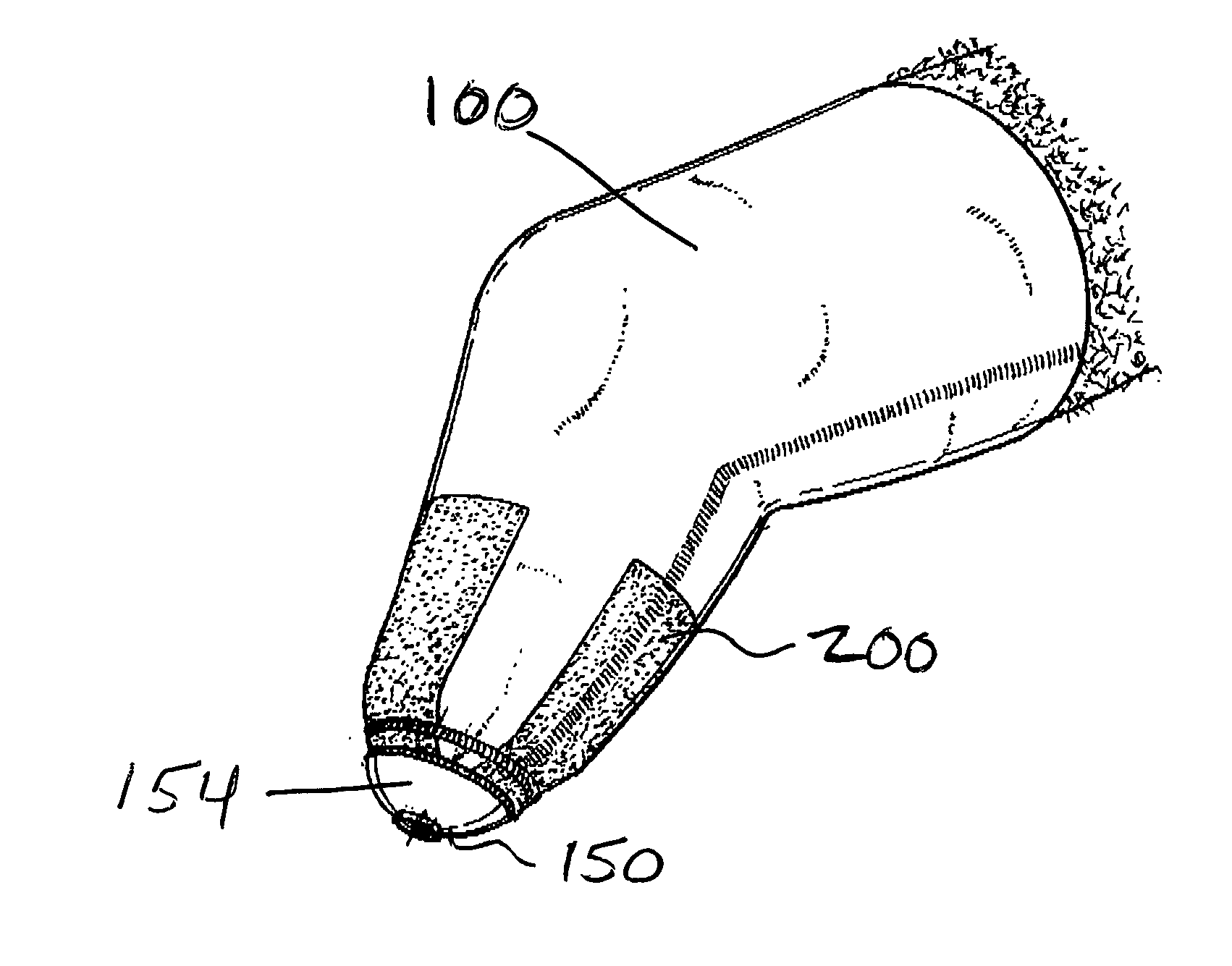
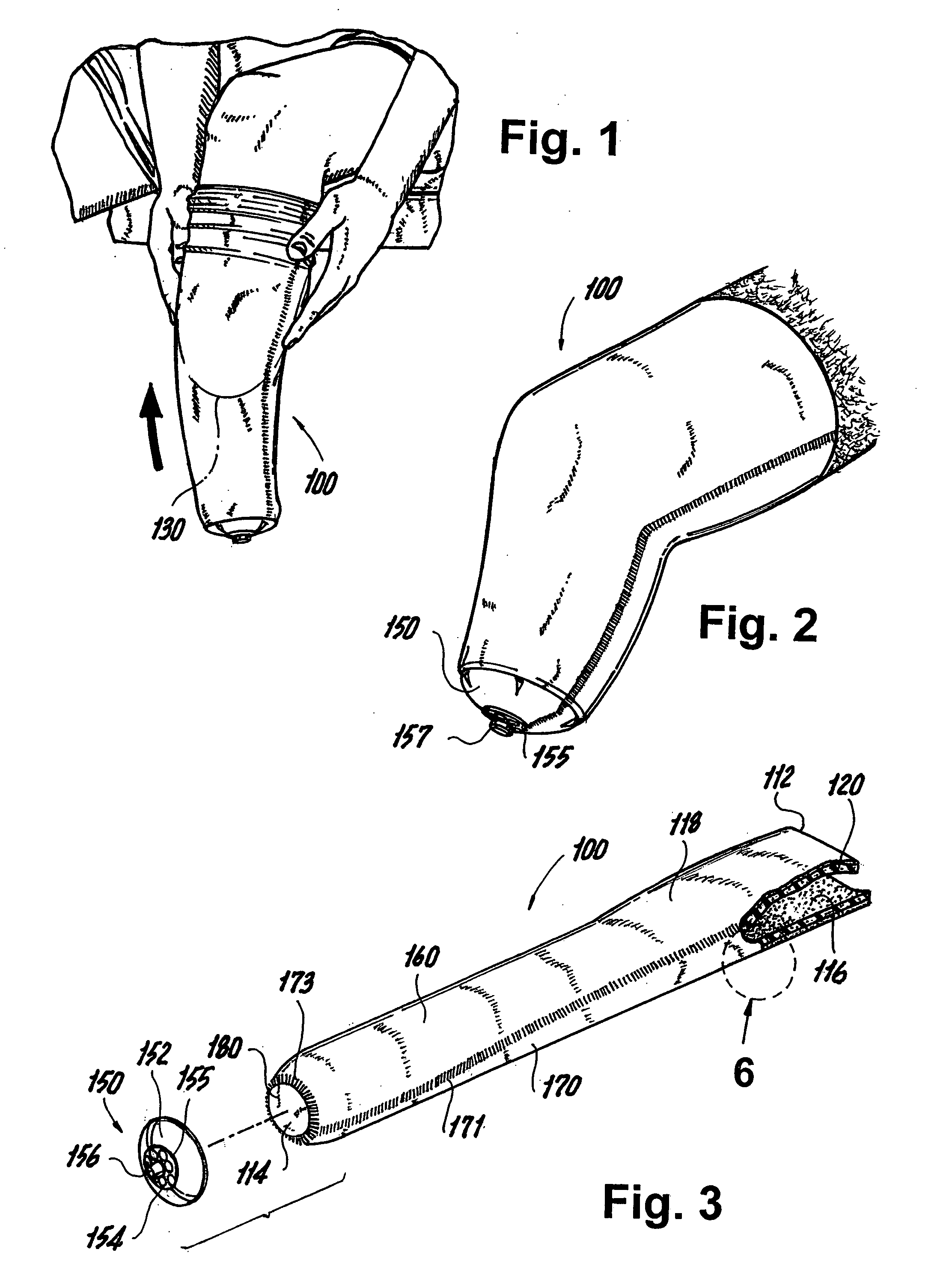
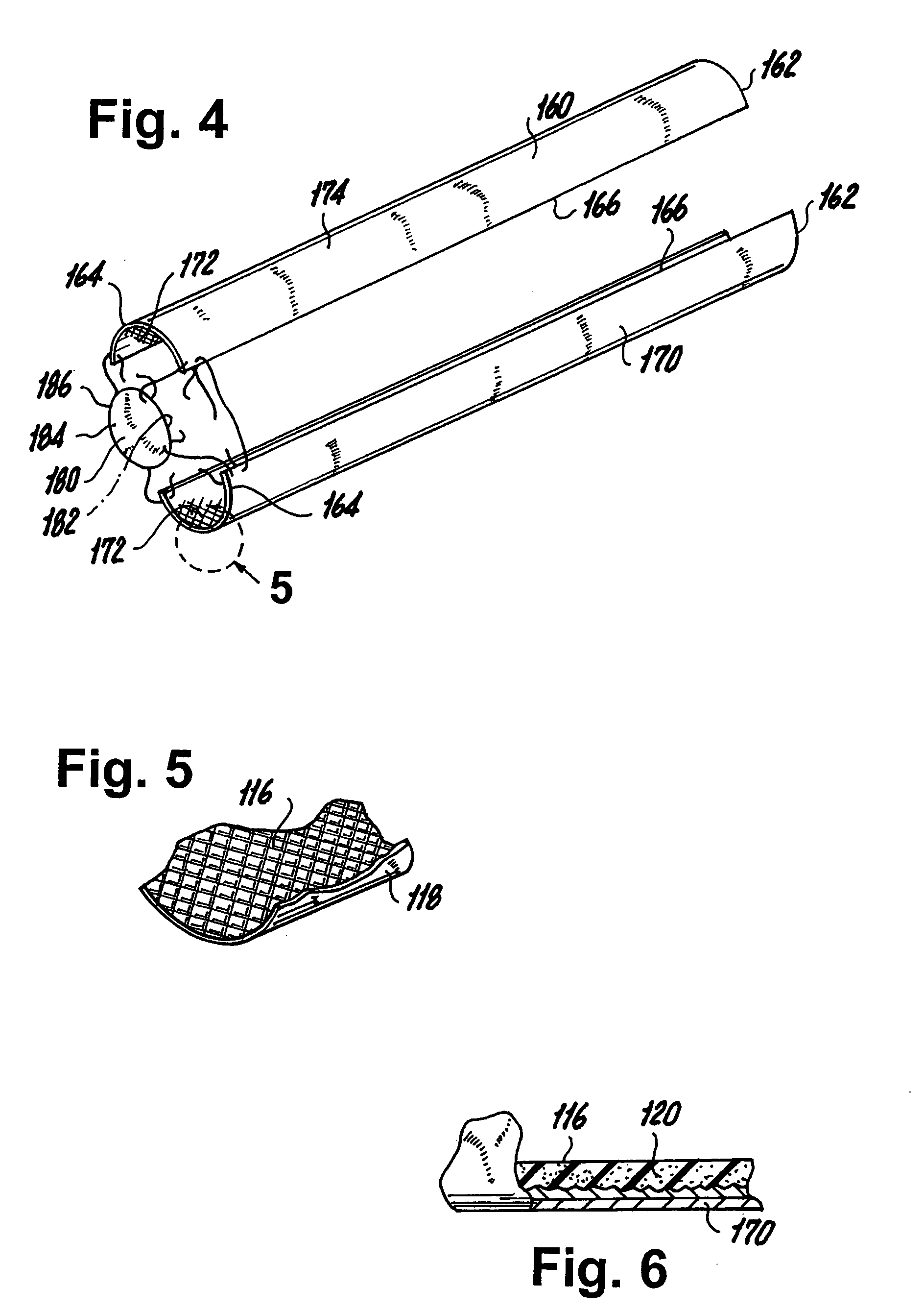
An improved liner (i.e., prosthetic liner) for covering a residual limb of an amputee is provided. According to one exemplary embodiment, the liner includes a fabric liner body that is formed of at least two fabric pieces and a stretch limiting element that is incorporated into an exterior surface of the distal end of the fabric liner body for reinforcement of the liner's distal end and for limiting stresses associated with distal end elongation. For example, the stretch limiting element can be in the form of a coating of a material that has limited flexibility and is integrally adhered to the outer surface of the fabric liner body such that the material seeps into the interior of the fabric liner body and optionally into any seams. Since the coating is integrally adhered to the fabric liner body and has an elasticity that is lower than that of the fabric liner body, the coating serves as a stretch limiting, anti-elongation element which counters forces that tend to result in the fabric liner body being stretched out during normal every day use.

Description

TECHNICAL FIELD [0001] The present invention relates generally to an article to be worn over an amputee's residual limb, and more particularly, to a liner that includes a surface reinforcement feature for limiting overall stretch of the article and for increasing wear characteristics of the article. BACKGROUND [0002] For the past decades, amputees have worn tubular sock-like articles over their residual limbs to provide additional comfort to the amputee when wearing a prosthetic limb. For many years, the tubular sock-like articles were formed of natural materials, such as cotton, wool, and cotton-wool blends; however, as synthetic materials become increasingly popular as a material of choice to form articles of apparel, including socks, the tubular sock-like articles were increasingly fabricated using synthetic materials. [0003] As is known, an amputee is typically fitted with a prosthetic member to be worn over the residual limb. In a below-knee (BK) prosthesis, an amputee's stump ...

Claims


Application Information

Patent Timeline
Patent Type & Authority Applications(United States)
IPC IPC(8): A61F2/00A61F2/50A61F2/78
CPCA61F2/5046A61F2/7812A61F2310/00047A61F2250/0018A61F2002/5055
Inventor SCHAFFER, STEPHEN P.MAY, BARRY A.ROMAN, THOMAS D.
Owner SILIPOS
Why Eureka
Try Eureka