Artificial knee joint

a knee joint and artificial technology, applied in the field of artificial knee joints, can solve the problems of amputee failure, uncontrollable bending of artificial knees, and inability to produce ideal gait characteristics, and achieve the effect of improving artificial knee joints

Active Publication Date: 2005-07-07
BLOORVIEW MACMILLAN CENT
View PDF59 Cites 22 Cited by
  • Summary
  • Abstract
  • Description
  • Claims
  • Application Information

AI Technical Summary

Benefits of technology

[0008] An object of the present invention is to provide an improved artificial knee joint. Although the invention is described with an intended application to the field of prosthetics, an adapted version of this knee mechanism may be used in orthotic applications.
[0009] According to the invention there is provided a prosthetic knee joint including stance phase control means comprising lock means for holding the knee in a straight condition and means determining the status of the lock means. The status determining means defines a control axis located so that the lock means is activated when a load imposed on the joint in use passes through a line posterior to the axis, and is deactivated when the load passes through a line anterior to the axis.
[0010] Preferably, the joint includes a main body and upper and lower coupling elements for attachment to respective upper and lower parts of a leg in which the joint is to be used. The upper coupling element is pivotally mounted to the main body for defining a knee axis and the lower coupling element is pivotally mounted to the main body for defining the control axis. The lock means acts between the upper and lower coupling elements for restraining the upper coupling element against movement about the knee axis when the load imposed on the joint passes through a line posterior to the control axis and to release the upper coupling element for movement about the knee axis when the load passes through a line anterior to the control axis.
[0011] The lock m...

Problems solved by technology

When standing or putting weight on the leg, as during the support-phase or stance-phase of the gait cycle it is undesirable for the prosthetic knee to bend uncontrollably as this will cause the amputee to fail.
However, this tends not to produce ideal gait characteristics.
However, this is not ideal be...

Method used


Image

  • Artificial knee joint
  • Artificial knee joint
  • Artificial knee joint

Examples


Embodiment Construction

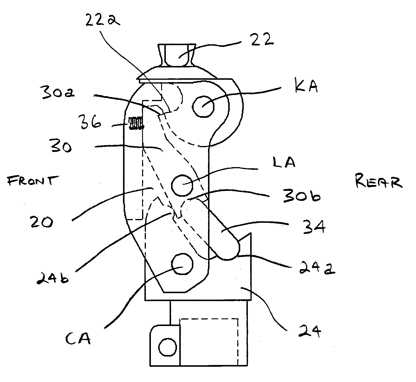
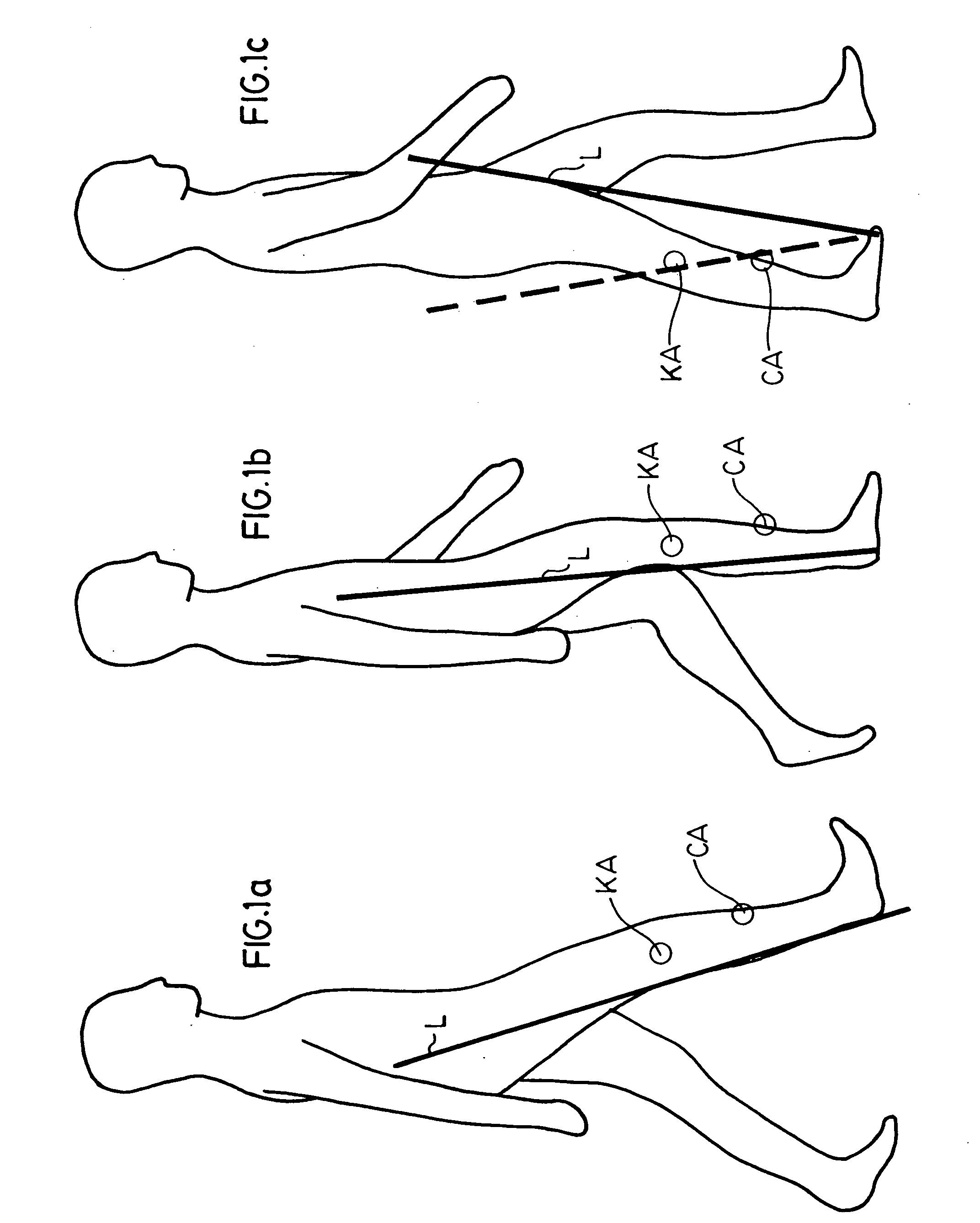
[0026] Reference will first be made to FIG. 1 is describing control of an artificial knee joint in accordance with the teachings of Radcliffe supra. As noted previously, the knee should be controlled so that during weight bearing, the knee lock is inactive when the fore foot is loaded, or similarly, the knee lock is activated only when the rear and / or mid-region of the foot is loaded. In the three diagrams that make up FIG. 1, a load line through the leg is denoted L. The pivot axis of the knee (knee axis) is denoted KA and a control axis is denoted CA. The knee axis KA and control axis CA are shown as white dots with CA below and in front of KA.

[0027] In diagram a) the knee would normally collapse since the load line L passes behind KA and causes a flexion moment at KA. However, the control is such that as long as there is a flexion moment at CA, a lock is activated at KA. The person rolls over the foot until the toe is loaded, (diagram c)), at which point the person will apply a ...


PUM


Abstract

A prosthetic knee joint including stance-phase control means comprising lock or latch for holding the knee in a straight condition, and means determining the status of the latch, said status determining means defining a control axis located so that the lock or latch is activated when a load imposed on the joint passes through a line posterior to said axis, and is de-activated when the load passes through a line anterior to said axis.

Description

CROSS-REFERENCE TO RELATED APPLICATIONS [0001] This application claims benefits from U.S. provisional application Ser. No. 60 / 523,093 filed Nov. 19, 2003 which is incorporated herein by reference in its entirety.FIELD OF THE INVENTION [0002] This invention relates to artificial knee joints for use by human amputees or as orthotic devices. BACKGROUND OF THE INVENTION [0003] In general, an artificial (prosthetic) knee joint will be prescribed for a person with a through-knee (TK) or an above-knee (AK) amputation, i.e. a person without a knee joint, shank or foot. The ability for the knee to bend or articulate allows for activities such as sitting; it also allows the leg to swing during the swing-phase of gait (walking or running). [0004] When standing or putting weight on the leg, as during the support-phase or stance-phase of the gait cycle it is undesirable for the prosthetic knee to bend uncontrollably as this will cause the amputee to fail. This is referred to as “stance-phase con...

Claims


Application Information

Patent Timeline
IPC IPC(8): A61F2/00A61F2/64A61F2/68
CPCA61F2/644A61F2/68A61F2220/0033A61F2002/30469A61F2002/6854A61F2002/30359
Inventor ANDRYSEK, JANNAUMANN, STEPHENCLEGHORN, WILLIAM L.
Owner BLOORVIEW MACMILLAN CENT
Why Eureka
Try Eureka