Pressurized flush system

a flushing system and pressurized technology, applied in the direction of flushing devices, water installations, constructions, etc., can solve the problems of not providing efficient water filling into the pressure, prior art systems do not efficiently discharge water, and prior art devices have no air-in provision, so as to achieve steady flushing volume and prevent leakage

Active Publication Date: 2005-07-14
LI FEIYU
View PDF12 Cites 15 Cited by
  • Summary
  • Abstract
  • Description
  • Claims
  • Application Information

AI Technical Summary

Benefits of technology

[0027] Among these, the pressure-controlled valve can attain a purpose of not to infill when flushing, and can make the flush volume more steady, preventing leakage when the flush valve cannot close due to the low pressure in the water supply system; the air-in device can fill some air into the pressure water vessel when water is filling; the anti-siphon device and the check valve device can prevent backflow from the pressure water vessel into the water supply system and making it polluted.
[0028] 4. In the flush valve of the present invention is set a water release tube, which, during the refill stage, can release water stored in the normal pressure cavity when flushing the toilet bowl. There is also a check valve in the water release tube, which can prevent backflow of wastewater from the toilet bowl into the normal pressure cavity caused by the resistance from the toilet bowl when flushing.

Problems solved by technology

Often prior art systems do not efficiently discharge water and often require a user to hold open a valve in order that water is fully discharged.
In addition, any prior art devices have no air-in provision.
This does not provide efficient water filling into the pressure.

Method used


Image

  • Pressurized flush system
  • Pressurized flush system
  • Pressurized flush system

Examples


Embodiment Construction

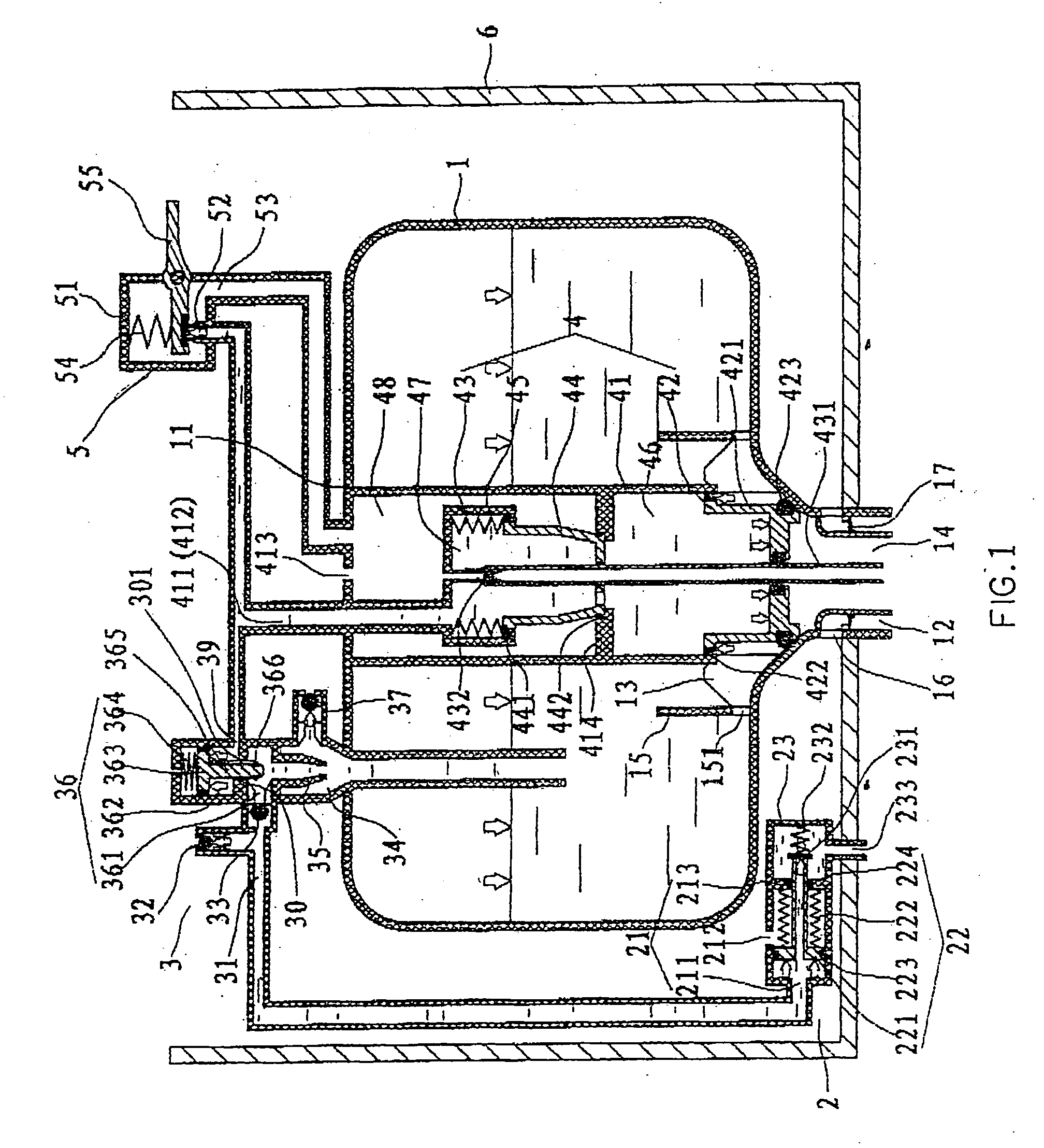
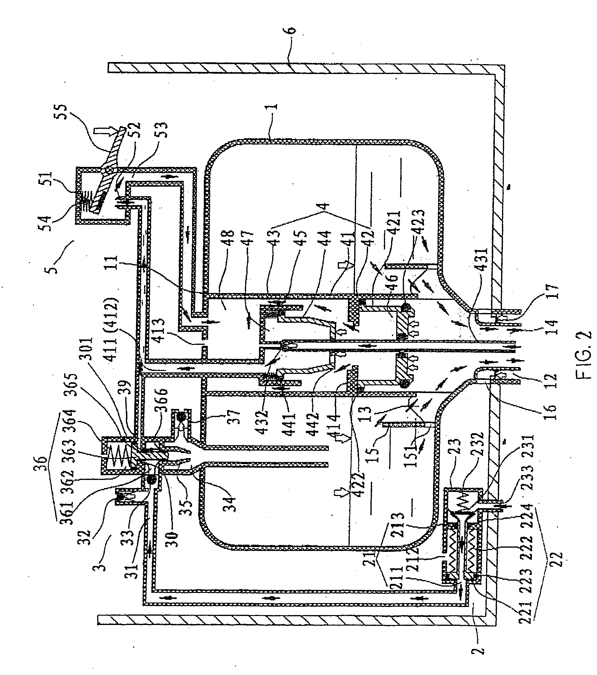
[0036] With reference to FIG. 6, there is shown a prior art pressurized flush system used in toilets that has been widely accepted due to its saving more water than a conventional normal pressure flush system.

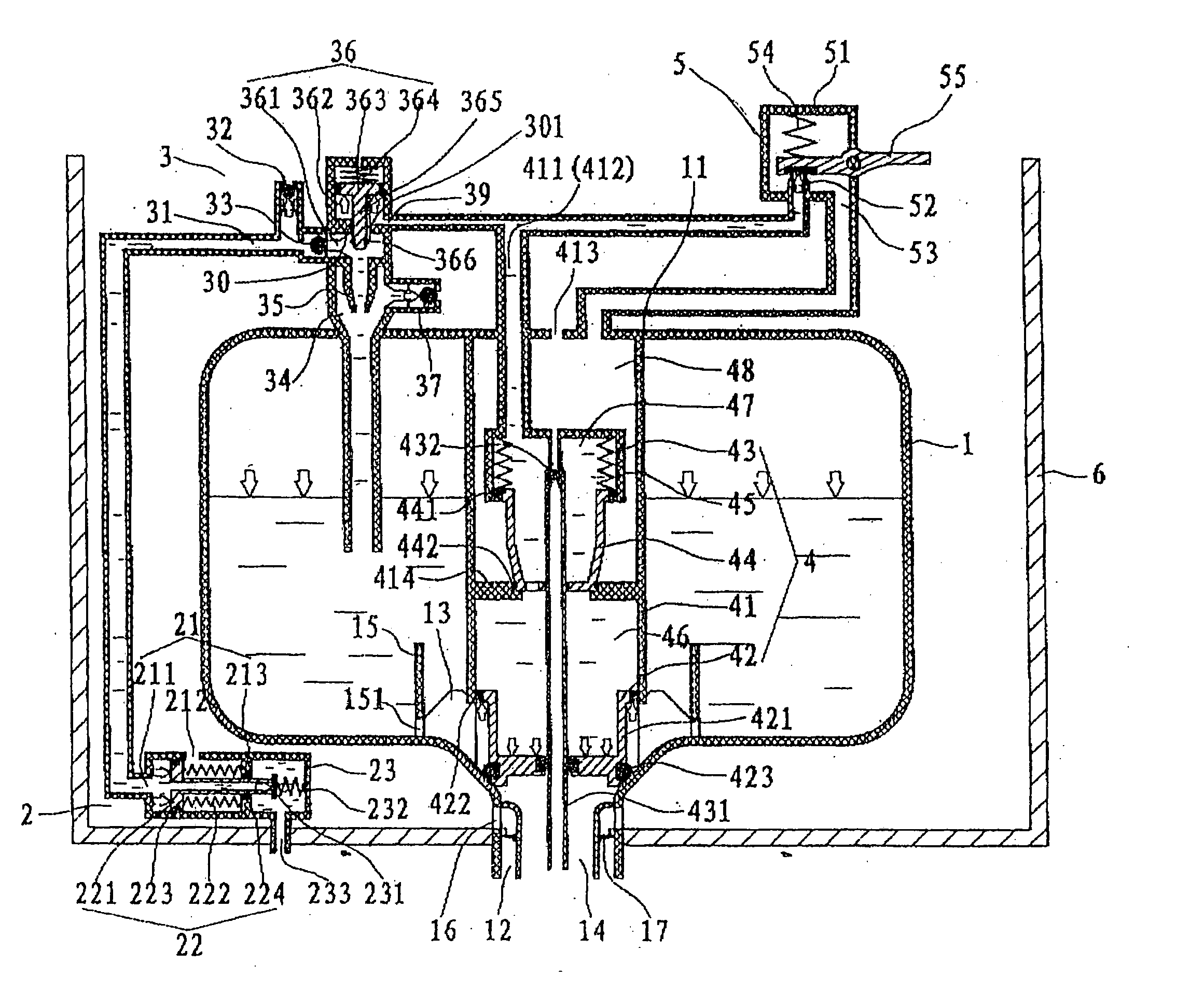
[0037] As shown in FIG. 6, this pressurized flush system comprises a pressure water vessel 1′ fixed in a ceramic tank 6′, an infill valve 2′, a flush valve 4′, and an open valve 5′ which can discharge the pressurized water from the flush valve 4′. The flush valve 4′ is fixed through the pressure water vessel 1′ and seals it. Above the outlet 14′ in the pressure water vessel 1′ is set a refill bar 15′, in the bottom of which is set at least one refill orifice 151.

[0038] The flush valve 4′ mainly includes a hollow valve body 41′ fixed in the pressure water vessel 1′, and a flush piston 42′ which is set in the valve body 41′ and can hermetically slide in it. The bottom of the flush piston 42′ can seal the outlet 14′ of the pressure water vessel 1′, and on the valve body 41′ are ...


PUM


Abstract

A pressurized flush system includes a pressure water vessel having an inlet and an outlet. An infill valve, an open valve, and a flush valve are provided with the flush valve disposed within the pressure vessel and in fluid communication with the infill valve and the open valve. The flush valve includes a hollow valve body and cooperating pistons controlling water discharge from the water vessel outlet. The cooperating pistons are disposed within the hollow valve body.

Description

[0001] The present application is a continuation of U.S. Provisional Patent Application Ser. No. 60 / 535,738 filed Jan. 8, 2004. This referenced patent application is to be incorporated into the present application in its entirety by this specific reference thereto.[0002] The present invention is generally related to pressurized flushed systems for toilets and is more specifically directed to a flushing system that maximizes the efficiency of effluent transport within a pressure baffle and discharge to a toilet bowl. [0003] Water conservation is an environmental consideration and has resulted in strict controls being placed on domestic water usages. [0004] Pressurized flushed systems have been developed to conserve water use. [0005] Often prior art systems do not efficiently discharge water and often require a user to hold open a valve in order that water is fully discharged. Accordingly, a user is required to cooperate with time delay operation in order to efficiently discharge the ...

Claims


Application Information

Patent Timeline
Patent Type & Authority Applications(United States)
IPC IPC(8): E03D3/04E03D3/10
CPCE03D3/10E03D3/04
Inventor LI, FEIYU
Owner LI FEIYU
Why Eureka
Try Eureka