
Device and method for ultrasonic inspection using profilometry data

a profilometry and ultrasonic technology, applied in the direction of instruments, specific gravity measurement, magnetic property measurement, etc., can solve the problems of affecting the accuracy of the image, the control device may produce an inaccurate representation of the internal structure of the test object, and the limitations of the ultrasonic transducer and control devi

Active Publication Date: 2005-07-14
WESTINGHOUSE ELECTRIC CORP
View PDF5 Cites 52 Cited by
  • Summary
  • Abstract
  • Description
  • Claims
  • Application Information

AI Technical Summary

Benefits of technology

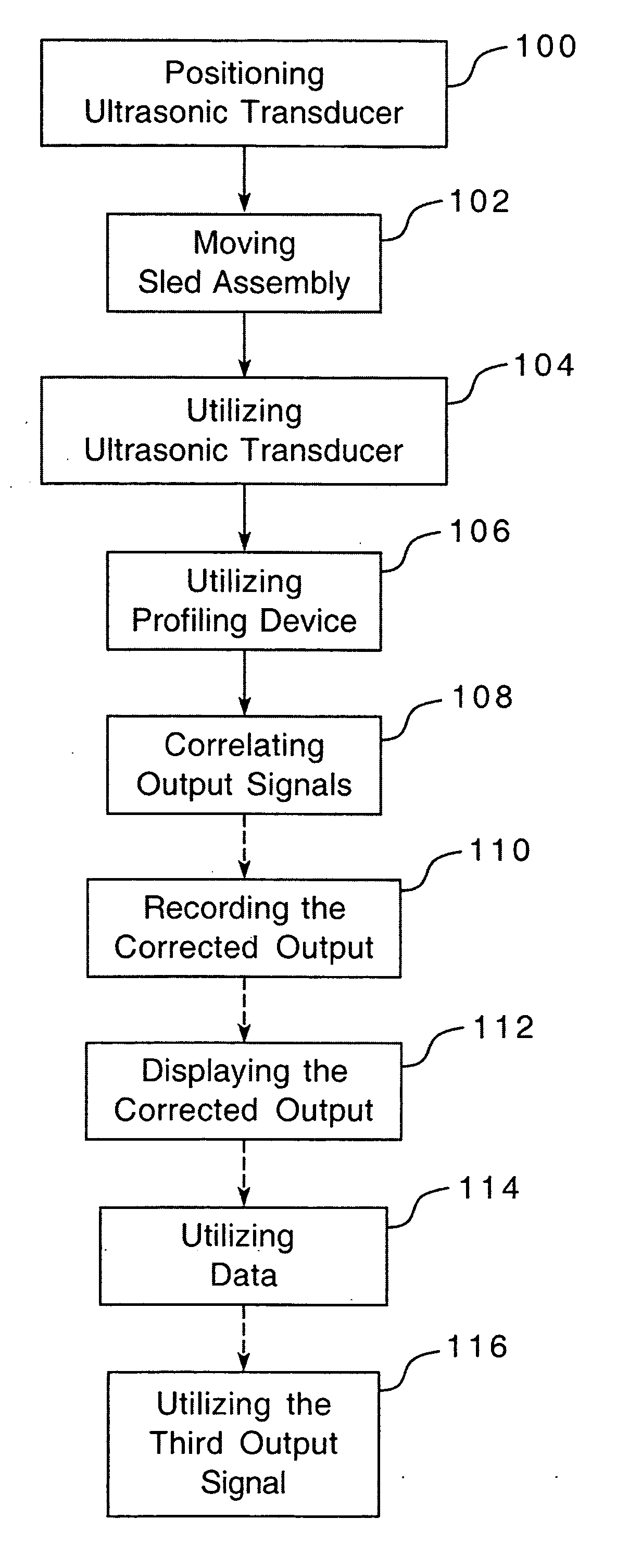
[0015] The control device is similar to those known in the art to the extent that the control device includes electronics structured to receive and interpret the output signals from the ultrasonic transducers. The control device is further structured to record and / or display the interpreted outputs, for example, but not limited to, on a display device such as a monitor. The control device is further structured, that is, it includes electronics designed to interpret the output from the profiling ultrasonic transducer and correct the surface ultrasonic transducer output based on the profile of the test object surface. In this manner, the ultrasonic testing assembly can be used to better determine the actual locations of defects and other internal structures within the test object.

Problems solved by technology

The ultrasonic transducer and control device, however, suffer from limitations that affect the accuracy of the image.
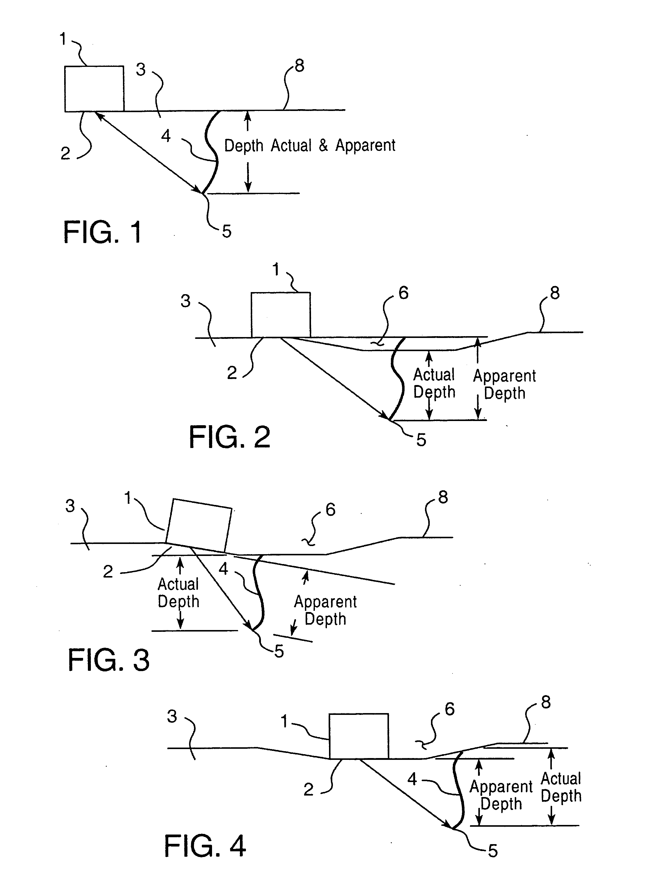
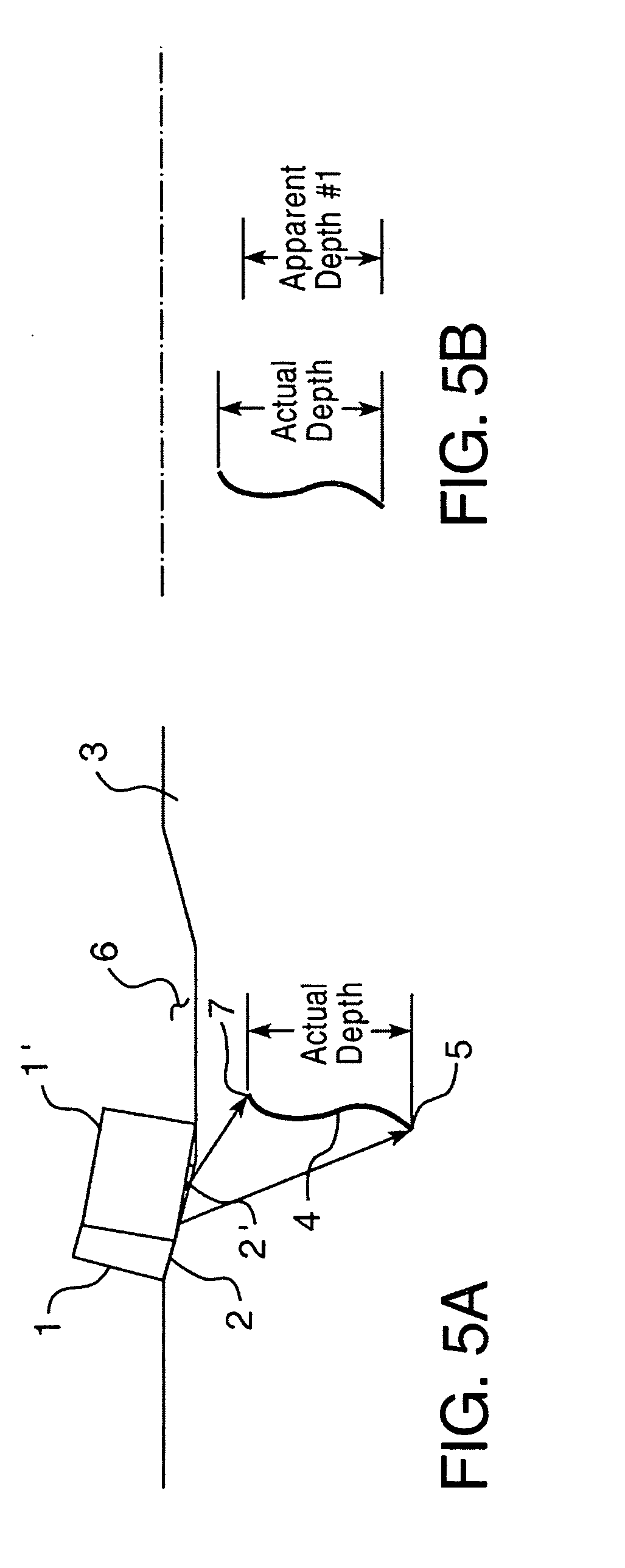
However, where the test object surface is uneven, the signal / response time is affected and the control device may produce an inaccurate representation of the test object's internal structure.
In this instance, the angle of the ultrasonic transducer 1 on the transition portion creates a slanted path for the signal and echo which, in turn, creates an inaccurate reading.

Method used


Image

  • Device and method for ultrasonic inspection using profilometry data
  • Device and method for ultrasonic inspection using profilometry data
  • Device and method for ultrasonic inspection using profilometry data

Examples


Embodiment Construction

[0027] As shown in FIG. 6, and an alternate embodiment shown in FIG. 8 (discussed below), an ultrasonic testing assembly 10 is structured to examine a test object 3 having a surface 8. Within test object 3 there is a defect 4, e.g. a crack. The defect 4 has a lower end 5 and a top end 7. The surface 8 has a normal portion 9 and a depression 6 with a transition portion 9a therebetween. It is noted that the size of the depression 6 is exaggerated. The ultrasonic testing assembly 10 includes a sled assembly 12, at least one surface ultrasonic transducer 14, at least one profiling device 16, and a control device 18. The sled assembly 12 is structured to support a plurality of ultrasonic transducers or other components, including the at least one surface ultrasonic transducer 14, and at least one profiling device 16. The sled assembly 12 has at least one support member 20 having a lower surface 22. The at least one support member 20 may, for example, be a frame assembly (not shown), but ...


PUM


Abstract

An ultrasonic testing assembly structured to examine a test object, wherein the test object has a surface, and the examination examines the structure of the test object under the surface as well as the profile of the surface. The ultrasonic testing assembly includes a sled assembly structured to support a plurality of ultrasonic transducers, the sled assembly including at least one support member having a lower surface, at least one surface ultrasonic transducer coupled to the sled assembly and structured to extend below the support member lower surface and further structured to engage the test object surface, the surface ultrasonic transducer structured to examine internal structure of the test object and provide a first output, at least one profiling device coupled to the sled assembly, the profiling device structured to measure the profile of the test object surface and provide a second output, and a control device structured to correlate the first output and the second output and to calculate a corrected output.

Description

CROSS-REFERENCE TO RELATED APPLICATION [0001] This application claims priority under 35 U.S.C. §119(e) to U.S. Provisional Patent Application Ser. No. 60 / 535,313, filed Jan. 9, 2004 entitled, THROUGHWALL SIZING USING PROFILOMETRY DATA.BACKGROUND OF THE INVENTION [0002] 1. Field of the Invention [0003] The present invention relates to a device and a method for ultrasonic inspection and, more specifically, to a device and a method for ultrasonic inspection wherein the device is structured to measure the profile of the object being tested and use that data to improve the results of the ultrasonic inspection device. [0004] 2. Background Information [0005] The use of non-destructive inspection devices which utilize ultrasonic vibrations is well known. Generally, an ultrasonic transducer, typically a piezoelectric crystal which is excited by an electrical pulse, is placed on the surface of a test object. The transducer alternately sends an ultrasonic signal and receives an echo. The piezo...

Claims


Application Information

Patent Timeline
IPC IPC(8): G01N9/24G01N29/06G01N29/265
CPCG01N29/0609G01N2291/044G01N29/265
Inventor NENNO, THOMAS W.MINOGUE, PATRICK M.RISHEL, RICK D.
Owner WESTINGHOUSE ELECTRIC CORP
Learn More