Method and system for controlling the operation of a valve

a valve and operation method technology, applied in the direction of ground installation, transportation and packaging, alighting gear, etc., can solve the problems of no control or adjustment during the arresting cycle, the system described above requires a great deal of maintenance, and the parts in the system are subject to a great deal of wear and tear, so as to reduce the force required to move the valve member

Inactive Publication Date: 2005-07-14
MAROTTA SCI CONTROLS
View PDF59 Cites 13 Cited by
  • Summary
  • Abstract
  • Description
  • Claims
  • Application Information

AI Technical Summary

Benefits of technology

[0034] In certain preferred embodiments, the valve member has an inlet-facing surface and a balancing surface opposite the inlet-facing surface. The balancing surface is d...

Problems solved by technology

In addition, the system described above requires a great deal of maintenance.
Due to the hammer-like action in shutting the valve, the parts in the system are subjected to a great deal of w...

Method used


Image

  • Method and system for controlling the operation of a valve
  • Method and system for controlling the operation of a valve
  • Method and system for controlling the operation of a valve

Examples


Embodiment Construction

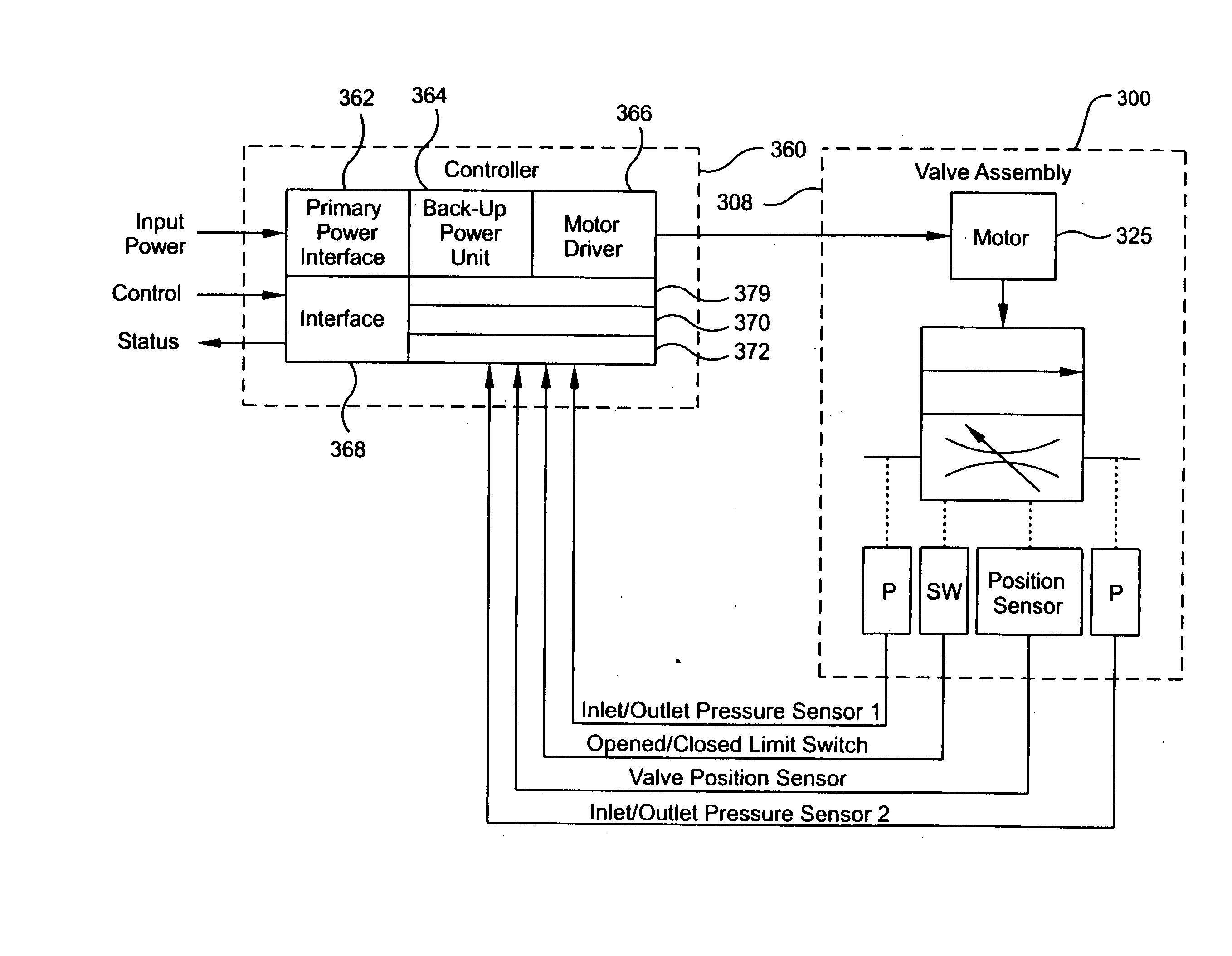
[0077] An embodiment of a system for reducing the speed of a moving craft is shown in FIGS. 4-15. As shown in FIG. 4, a pendant 110 comprising a cable is arranged with a hydraulic system 118 for transferring energy from the pendant 110 to a control mechanism 119 for controllably releasing energy from the hydraulic system 118. In the embodiment shown, the control mechanism comprises a valve 126 arranged in the hydraulic system 118. The pendant 110 applies pressure to the fluid in the hydraulic system 118 and the valve controls the flow of the fluid while the speed of the craft is being decreased.

[0078] The valve 126, best seen in FIG. 5, has an inlet 128 and an outlet 132 and comprises a closure or valve member 140 for opening and closing the inlet 128 of the valve 126. When the valve 126 is open, fluid from the hydraulic system 118 is allowed to pass from the inlet 128 to the outlet 132 of the valve 126. The valve 126 includes a housing 145 connected to the hydraulic system 118 com...


PUM


Abstract

A speed reduction system for decreasing the speed of a moving craft has a craft engaging device, a control mechanism, and a hydraulic energy transfer system adapted to transmit energy from the craft engaging device to the control mechanism. The control mechanism is adapted to actively control release of energy from the hydraulic energy transfer system during the decrease of the speed of the craft. A method of controlling the operation of a valve includes adjusting the valve during the operation of the valve after comparing a condition to a desired condition determined by a profile. A hydraulic valve has a valve member defining passages arranged to balance the force of the fluid pressure acting on the valve member and an actuator connected to the valve member. A valve control system includes a controller and a driver arranged with the controller. The position of the valve is adjusted during a predetermined cycle to control the operation of the valve.

Description

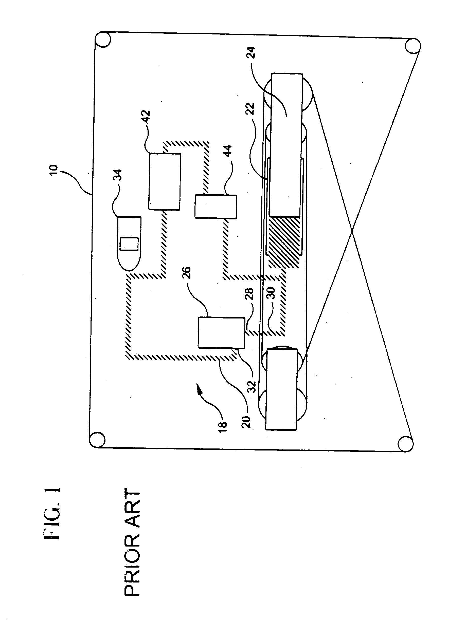
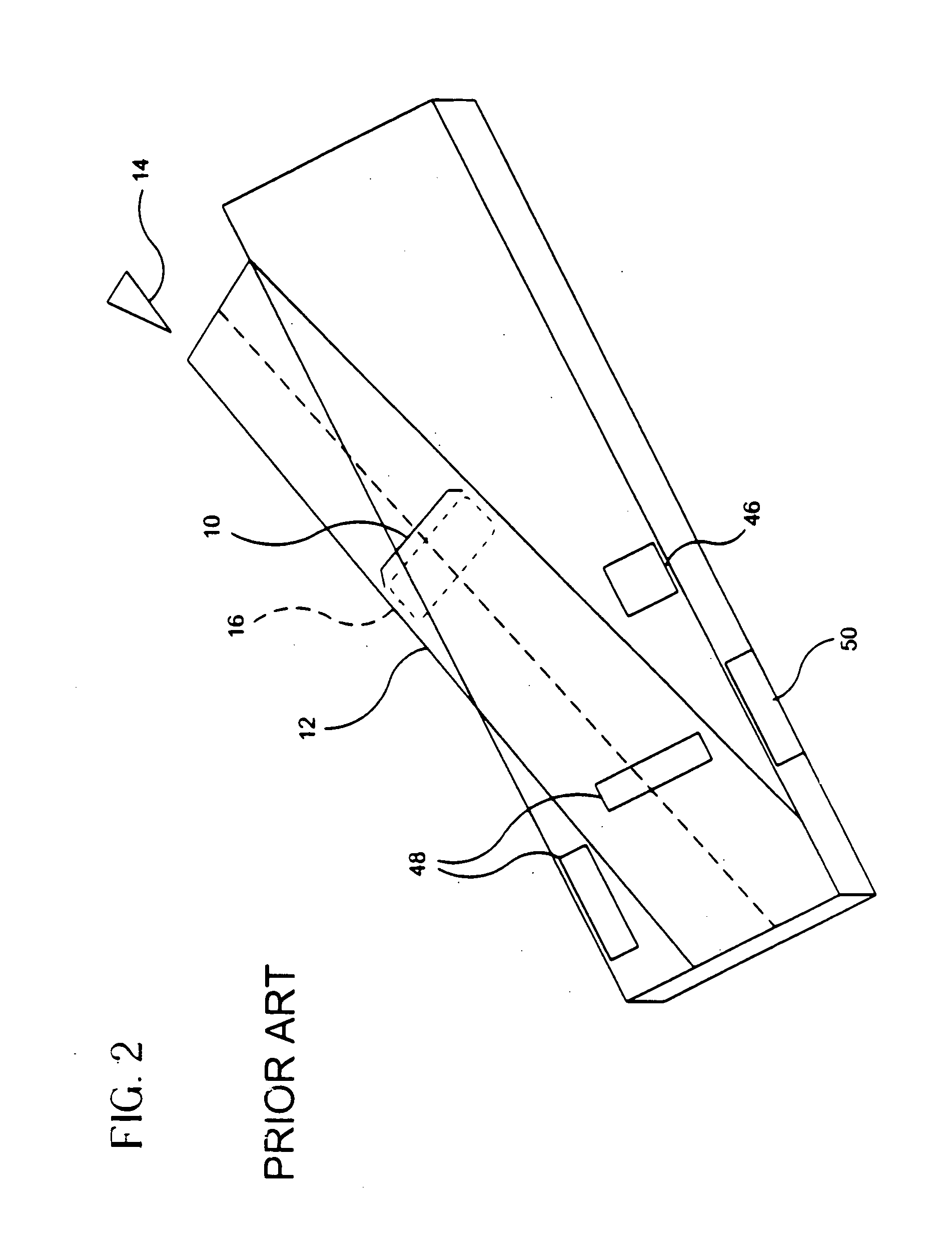
CROSS-REFERENCE TO RELATED APPLICATIONS [0001] This application is a divisional application of U.S. application Ser. No. 10 / 354,339 filed on Jan. 30, 2003, which claims the benefit of U.S. Provisional Application No. 60 / 354,054, filed Jan. 31, 2002, and U.S. Provisional Application No. 60 / 376,094, filed Apr. 26, 2002, the disclosures of which are both hereby incorporated by reference herein.FIELD OF THE INVENTION [0002] The present invention relates to systems for decreasing the speed of a moving craft, as well as to methods and apparatus for controlling the operation of such systems and for controlling the operation of any valve. BACKGROUND OF THE INVENTION [0003] A schematic of a prior art system for arresting a moving craft on an aircraft carrier is shown in FIG. 1. A deck pendant 10 extends across the deck of the aircraft carrier. As an aircraft 14 approaches for a landing, a tail hook from the aircraft engages the pendant 10 on the deck 12 of the aircraft carrier (see FIG. 2). ...

Claims


Application Information

Patent Timeline
IPC IPC(8): B64F1/02
CPCB64F1/02B64F1/027B64F1/029
Inventor TARTAGLIA, PETERRALEA, MIHAI
Owner MAROTTA SCI CONTROLS
Why Eureka
Try Eureka