Living hinge member and suspension

a hinge member and living technology, applied in the direction of friction roller based transmission, steering device, cycle equipment, etc., can solve the problems of large number of parts, mechanical complexity, unsatisfactory comfort and optimum performance of conventional rigid arrangement,

Inactive Publication Date: 2005-07-14
BLACKROCK KELSO CAPITAL CORP AS AGENT
View PDF23 Cites 20 Cited by
  • Summary
  • Abstract
  • Description
  • Claims
  • Application Information

AI Technical Summary

Problems solved by technology

Further, the conventional rigid arrangement is unsatisfactory for comfort and optimum performance on rough terrain.
These linkage systems have several drawbacks in that they are mechanically complicated, require a large number of parts, and add unwanted weight.
When chain stay tubes flex over their entire length, it is difficult to dictate the performance characteristics of the rear suspension.

Method used


Image

  • Living hinge member and suspension
  • Living hinge member and suspension
  • Living hinge member and suspension

Examples


second embodiment

[0086] In the second embodiment, to form the preform, first, one carbon tubular sleeve having a length preferably of about 18 inches is placed over a mandrel. Alternatively, a carbon sheet may be used such that the sheet is wrapped around the silicone bladder and then tacked in place by using a soldering iron or similar heating element to join the mating edges of the carbon sheet to form a first tubular layer. FIG. 11A shows a schematic of the first layer A around the silicone bladder S.

[0087] Next two uniglass sheets having a length of 7 inches are wrapped around the first layer at each end thereof and each sheet is placed 1.25″ from the center of the preform to form a second layer. This is done by first tracking one edge of each sheet to the carbon layer. Second, the uniglass sheet is wrapped around the layer and tacked again to join the mating ends of the uniglass sheet together to form the second layer. FIG. 11B shows a schematic of the first layer A and the second layer B aroun...

first embodiment

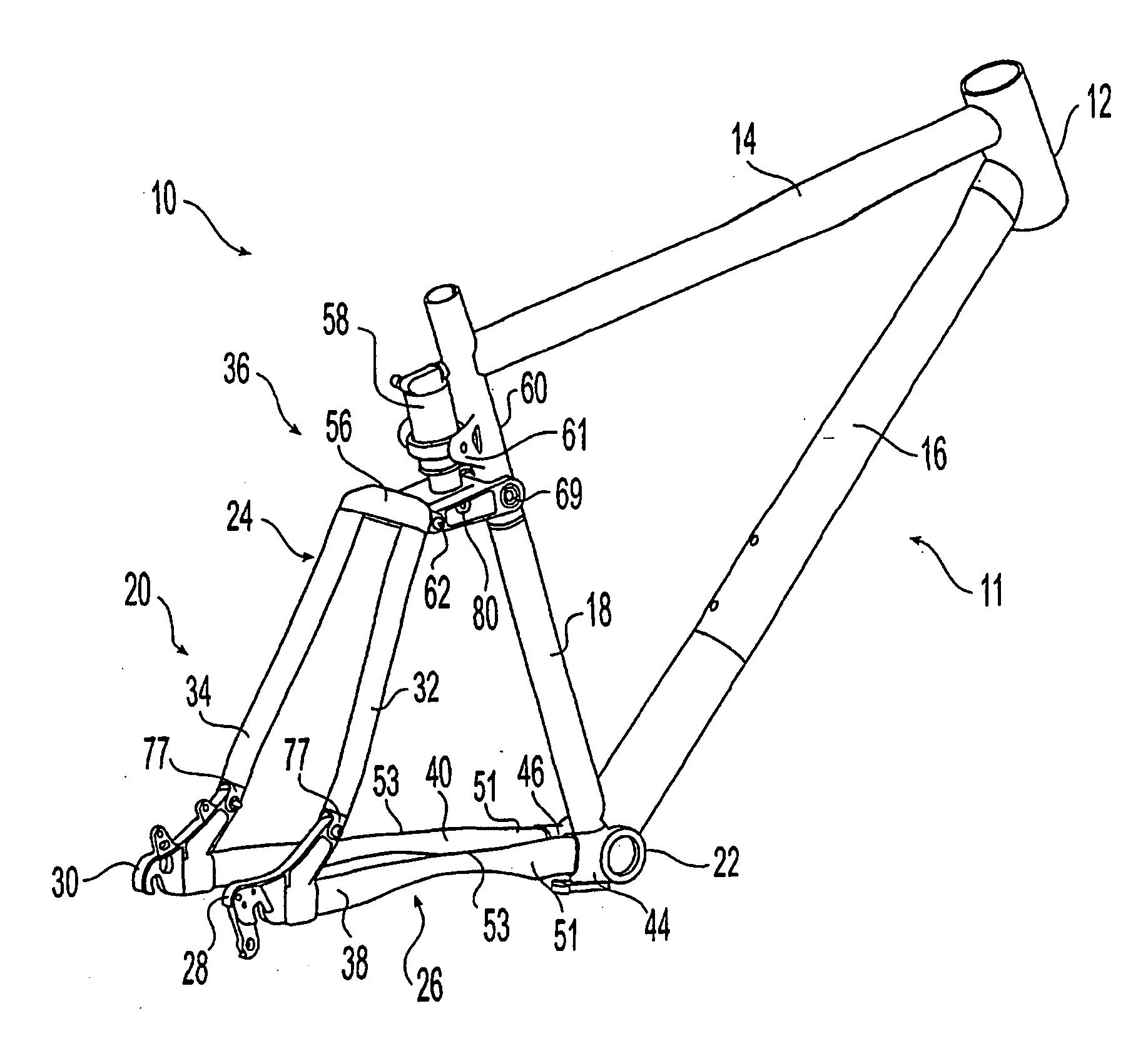
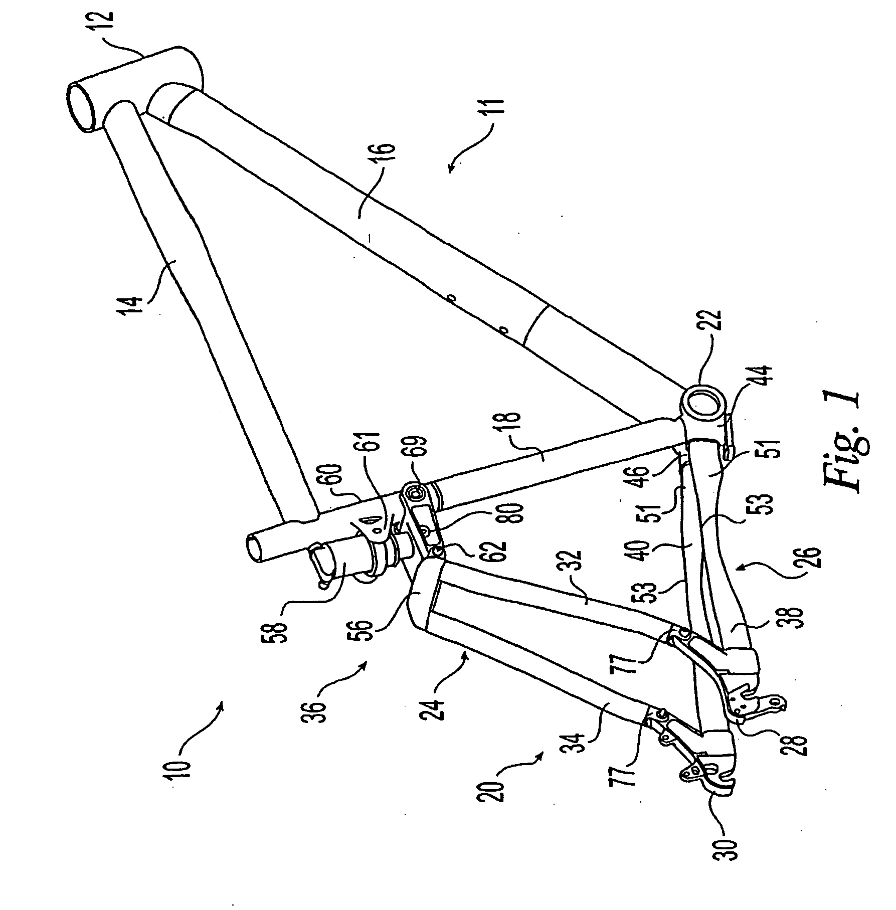
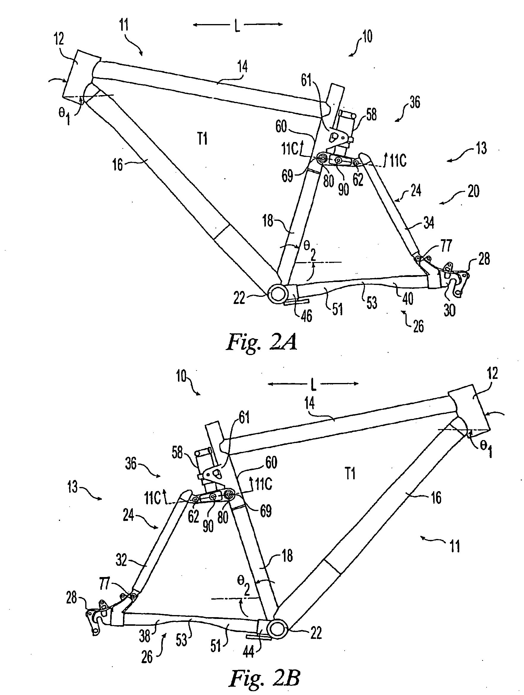
[0098] For example, with the first embodiment, an aluminum, hollow, oval tube having a length of approximately 1.75 inches that is about 0.7 inches tall, about 0.5 inches wide, and about 0.03 inches thick may be bonded into the chain stay using acrylic adhesive. One acrylic adhesive that may be used is Plexus Brand MA310. Other bonding materials can be used that are known in the art. The aluminum reinforcement tube can be placed in the chain stay closer to the bottom bracket 22 opposite the dropouts 28,30 or alternatively placed closer to the dropouts 28,30. Furthermore, the chain stay can be reinforced near the bottom bracket and the near the dropouts. Other dimensions, materials or locations for the reinforcement can be used and are not limited to the examples discussed. For example, the reinforcement may extend the entire length of the tube or only partially along the length. It may be positioned at both ends, or at a number of locations along the length. Types of reinforcement t...


PUM


Abstract

A structural member (38, 40) is designed to have a first portion having a first composite layup, a second portion having a second composite layup, and at least one center portion having at least a third composite layup such that it can flex near a desired point of the structural member. The structural member may be used as a chain stay (26) in a bicycle frame (10). The chain stays are designed to have a geometry that will allow for flexing or bending at or in the vicinity of a desired point. They may be pre-loaded for flex in both a positive and negative direction. The chain stays are designed having a varying cross sectional area. The bending or flexing location of the chain stays has a narrower height from the side view than the ends of the chain stay allowing the chain stay to flex. Additionally, the bending or flexing location has a wider width from the top view than the ends of the chain stay for additional torsional and lateral stiffness.

Description

CROSS-REFERENCE TO RELATED APPLICATIONS [0001] This application is a continuation of U.S. patent application Ser. No. 10 / 258,675, filed Oct. 25, 2002.TECHNICAL FIELD OF THE INVENTION [0002] This invention relates generally to a flexural structural member and a method of making a flexural structural member. More particularly, the invention is directed to a chain stay for use in a rear suspension of a bicycle frame. BACKGROUND OF THE INVENTION [0003] Conventional bicycle frames use tubes joined into closed frameworks to interconnect the components (front fork / handlebar assembly, seat, crankset, rear wheel) and transmit the loads therebetween. The tubes also keep the components in spacial relation to one another, i.e., they maintain the components in relative proximity. [0004] The traditional bicycle frame includes a top tube, a relatively short head tube, a seat tube, a down tube, a bottom bracket, a pair of chain stay tubes, a pair of dropouts, and a pair of seat stays. The top tube ...

Claims


Application Information

Patent Timeline
Patent Type & Authority Applications(United States)
IPC IPC(8): B62K19/16B62K19/30B62K25/26B62K25/30
CPCB62K19/16B62K25/30B62K25/26B62K19/30
Inventor PARKIN, MICHAEL JAMES
Owner BLACKROCK KELSO CAPITAL CORP AS AGENT
Why Eureka
Try Eureka