Wind turbine generator system

a generator system and wind turbine technology, applied in the direction of electric generator control, dynamo-electric converter control, instruments, etc., can solve the problems of reducing the availability of the wind turbine generator system and the inability to generate power, so as to achieve a synchronous operation with the grid

Active Publication Date: 2005-07-14
HITACHI IND PROD LTD
View PDF12 Cites 40 Cited by
  • Summary
  • Abstract
  • Description
  • Claims
  • Application Information

AI Technical Summary

Benefits of technology

[0004] An aspect of the present invention provides a wind turbine generator system employing a

Problems solved by technology

Thus, there may be intervals in which power cannot be generated though wind

Method used


Image

  • Wind turbine generator system
  • Wind turbine generator system
  • Wind turbine generator system

Examples


first embodiment

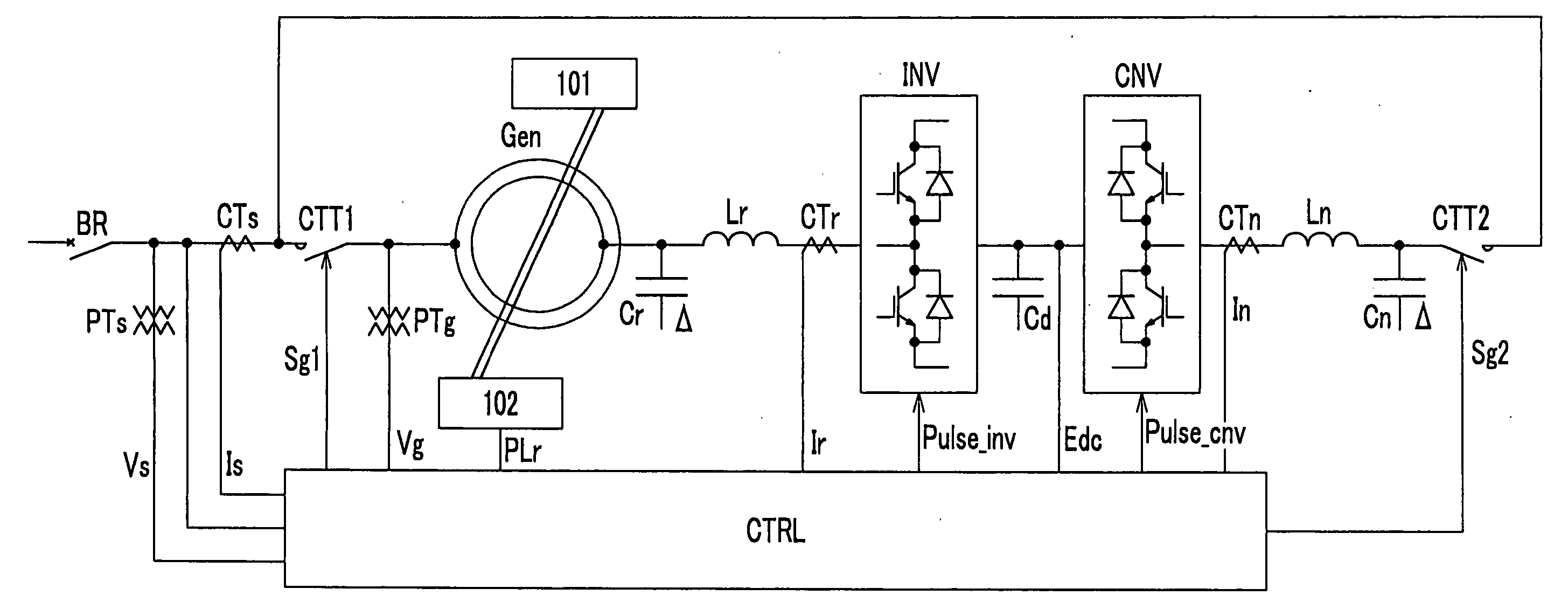
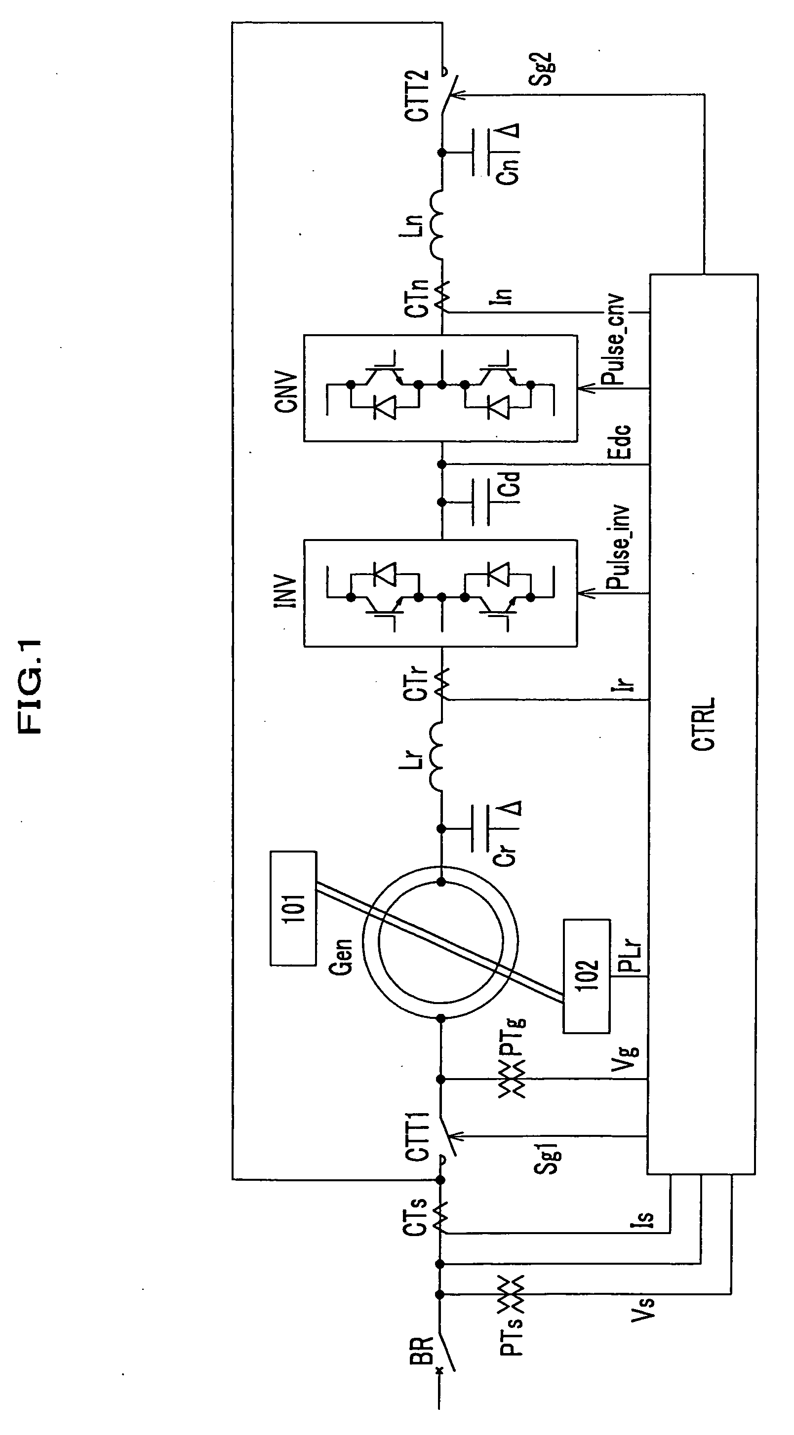
[0017] Electric wirings and respective sections of a wind turbine generator system for generating an electric power will be described with reference to FIG. 1. A wind turbine generator Gen according to this embodiment is of a doubly fed type of which three phase outputs from a stator are connected to a secondary side of a magnet contactor CTT1 switchable in response to a switch control signal. A primary side of the magnet contactor CTT1 is connected to a primary side of a magnet contactor CTT2 and to a secondary side of a breaker BR of which primary side is connected to a grid (an AC line).

[0018] The breaker BR has such a function that, upon a flow of an excessive current, a circuit connected to the breaker BR is opened to cut off a current flowing therethrough and, upon closing the breaker BR, power is supplied to the control unit CTRL of the wind turbine generator system and the magnetic contactor CTT1.

[0019] The secondary side of the magnet contactor CTT2 is connected to an AC ...

second embodiment

[0063] A wind turbine generator system according to a second embodiment has substantially the same structure as that of the first embodiment except the part of the synchronizing controller SYNC as shown in FIG. 6. More specifically, amplitudes and phases are detected with discrete Fourier transformers 601a and 601b, which receive the α term Vα of the grid voltage (50 / 60 Hz) and the stator voltage Vgu to calculate fundamental components to be compared. In this structure, only fundamental components are used for judgment for synchronizing and amplitude equalization, wherein the voltage amplitudes and phases are independently detected. As a result, the phase control can be provided in parallel to the amplitude equalization substantially at the same time.

[0064] As described above, the stator voltage Vgu is equalized in amplitude to and synchronized with the grid voltage, using one phase of grid voltage. Thus, the use of only one phase of the grid voltage provides equalization in amplit...


PUM


Abstract

To shorten a startup interval to reach a synchronizing condition, a phase difference and an amplitude difference between the grid voltage and the stator voltage of one phase of a winding are obtained. The difference in amplitude is decreased prior to or in parallel to synchronizing the stator voltage with the grid voltage. The calculated compensation phase compensation value is used as an initial value for synchronizing at the next synchronizing operation.

Description

FIELD OF THE INVENTION [0001] This invention relates to a wind turbine generator system using a doubly fed generator which provides easiness in synchronizing with a grid voltage. BACKGROUND OF THE INVENTION [0002] Doubly fed generators can output at their stator an AC voltage having the same frequency as that in a grid voltage frequency by exciting a rotor winding with a slip frequency by a converter and provide relative freedom of the rotational frequency and reduction in capacity of a converter. Japanese laid-open patent application publication No. 2000-308398 discloses such a doubly fed generator. Further, due to the relative freedom of the rotational frequency in generation operation and the reduction in capacity of the converter, the doubly fed generator is used for wind turbine generators. U.S. Pat. No. 6,566,764 discloses such a wind turbine generator system. [0003] In the conventional wind turbine generator system employing a doubly fed generator, a converter has a lower cap...

Claims


Application Information

Patent Timeline
IPC IPC(8): F03D9/00F02C6/00F03D7/00F03D7/02G05F5/00H02P9/00H02P9/04H02P9/08H02P9/14H03B5/00
CPCF03D7/026F03D9/003F05B2270/337H02P2101/15H02P9/10Y02E10/723H02P9/007F03D9/255Y02E10/72
Inventor ICHINOSE, MASAYAFUTAMI, MOTOOSAKAI, HIROMITSU
Owner HITACHI IND PROD LTD
Why Eureka
Try Eureka