Impact energy absorbing structure of vehicle frame member

Active Publication Date: 2005-07-14
NISSAN MOTOR CO LTD
View PDF13 Cites 30 Cited by
  • Summary
  • Abstract
  • Description
  • Claims
  • Application Information

AI Technical Summary

Benefits of technology

[0006] However, changing the material, the plate thickness and the like of the frame member, or adding the reinfo

Problems solved by technology

However, changing the material, the plate thickness and the like of the frame member, or adding the reinforci

Method used


Image

  • Impact energy absorbing structure of vehicle frame member
  • Impact energy absorbing structure of vehicle frame member
  • Impact energy absorbing structure of vehicle frame member

Examples


Example

[0017] An embodiment of the present invention will be explained below with reference to the drawings, wherein like members are designated by like reference characters.

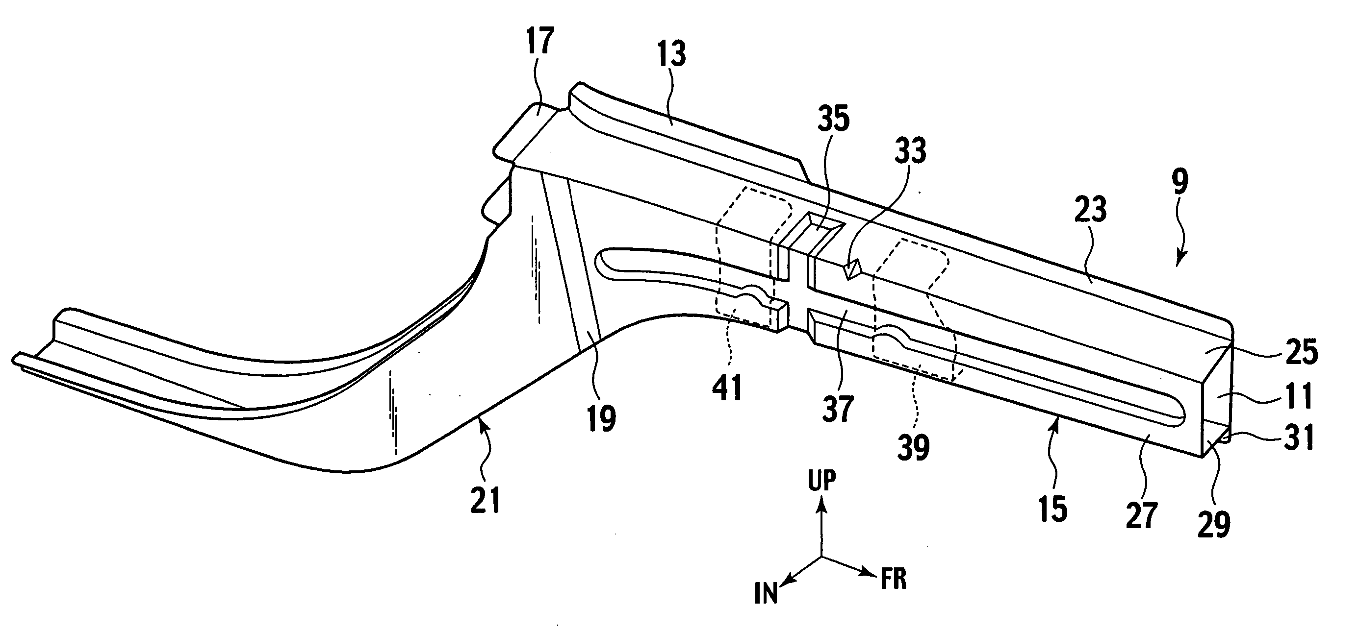
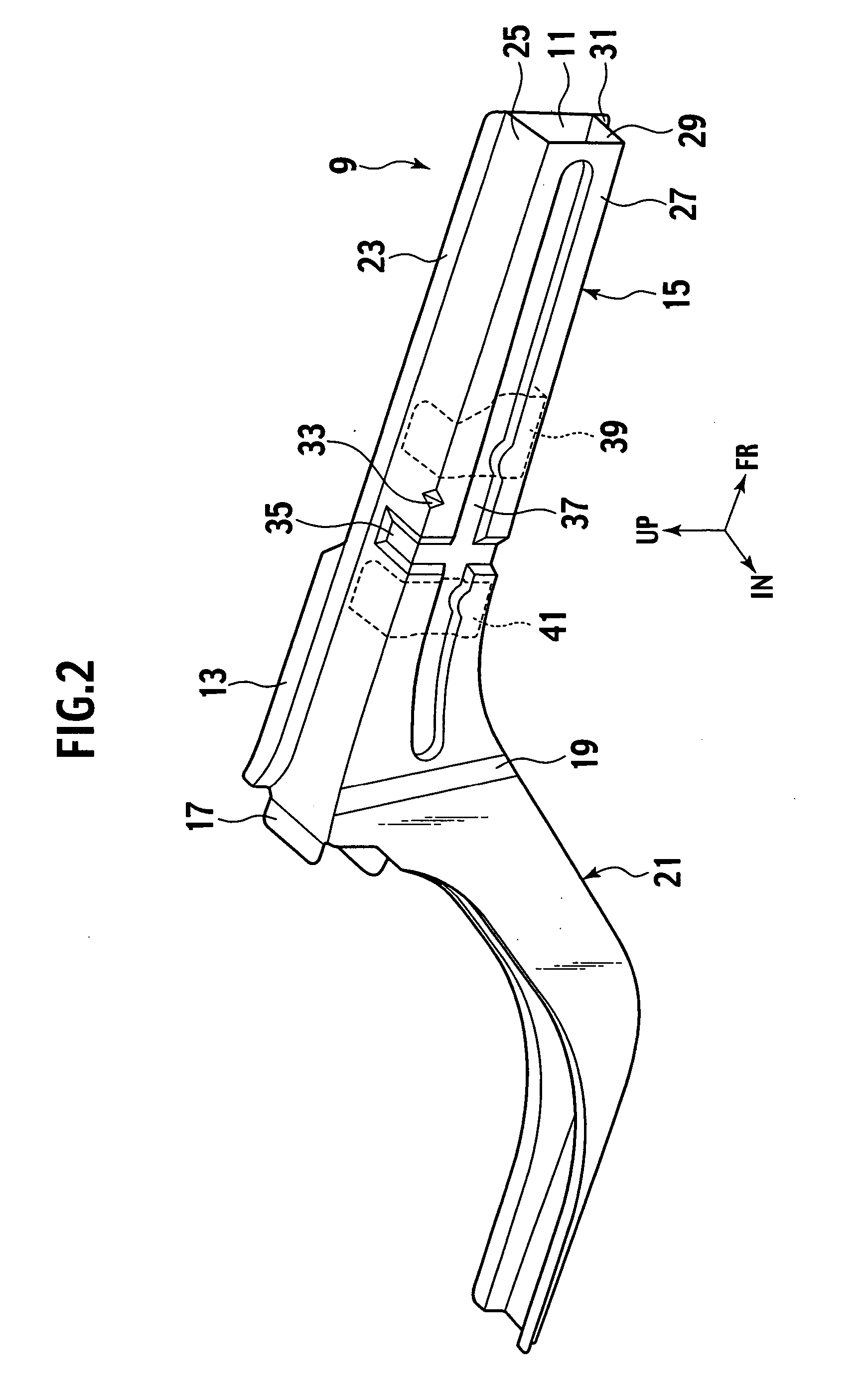
[0018] First of all, a description will be given of a front side member on which a bead for inducing and promoting a bending deformation thereof (hereinafter referred to as a bending deformation promoting bead) and a bead for inducing and promoting an axial deformation or buckling thereof (hereinafter referred to as an axial deformation promoting bead) are formed, and on which a reinforcement panel is arranged corresponding to the bending deformation promoting bead. This front side member can be mounted mainly on a vehicle lighter in weight.

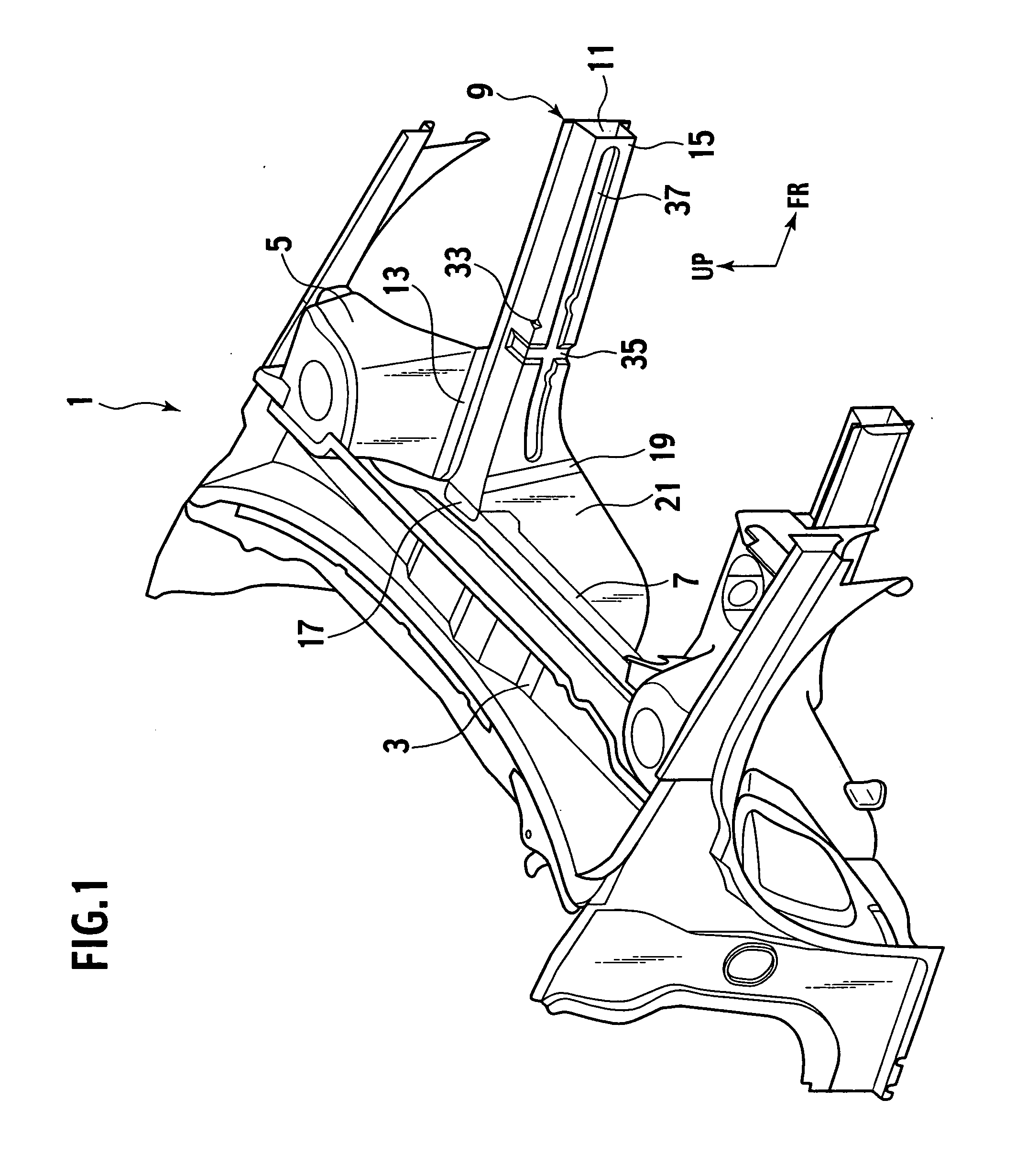
[0019] As shown in FIG. 1, in a front portion of a vehicle body 1, a cowl box 3 is extended in the vehicle transverse direction. Strut towers 5 are arranged in front of the right and left ends of the cowl box 3, respectively. In addition, a cross member 7 is extended in the vehicl...


PUM


Abstract

An impact energy absorbing structure of a frame member of a vehicle, which includes: a first bead formed on the frame member, which promotes bending deformation of the frame member when an impact load is inputted in an axial direction thereof; a second bead formed on the frame member, which promotes axial deformation of the frame member when the impact load is inputted in the axial direction thereof; and a reinforcement panel attached to the frame member. The frame member is configured to accommodate the reinforcement panel both in a first position beside the first bead and on the side from which the impact load is inputted, and in a second position where the first bead is reinforced with the reinforcement panel.

Description

BACKGROUND OF THE INVENTION [0001] 1. Field of Invention [0002] The present invention relates to an impact energy absorbing structure of a structural frame member of a vehicle, such as an automobile. [0003] 2. Description of Related Art [0004] Due to the differences in body weight and in engine specifications, reaction forces, deformation modes, crushing characteristics and the like of vehicle structural frame members at frontal collision of the vehicle, are different from one vehicle to another, depending on a required collision performance of the vehicle. [0005] In Japanese Patent Application Laid-open Publication No. 10-244955, differences in required reaction force characteristics between vehicle models, are dealt with by changing plate thickness, material and the like of the frame member, or by adding a reinforcing member such as a reinforcement panel. SUMMARY OF THE INVENTION [0006] However, changing the material, the plate thickness and the like of the frame member, or adding...

Claims


Application Information

Patent Timeline
IPC IPC(8): B60K5/12B60R13/02B60R19/18B60R21/02B60R21/04B60R21/045B60R21/05B60T1/02B62D1/19B62D21/15
CPCB62D21/152
Inventor YASUKOUCHI, SATOSHITACHIZAWA, HIROYUKI
Owner NISSAN MOTOR CO LTD
Why Eureka
Try Eureka