
Method and system for wireless pairing

a wireless communication and wireless communication technology, applied in data switching networks, digital transmission, substation equipment, etc., can solve the problems of inability to generate encryption keys, too small in size, and additional costs

Active Publication Date: 2005-07-14
VIA TECH INC
View PDF12 Cites 194 Cited by
  • Summary
  • Abstract
  • Description
  • Claims
  • Application Information

AI Technical Summary

Benefits of technology

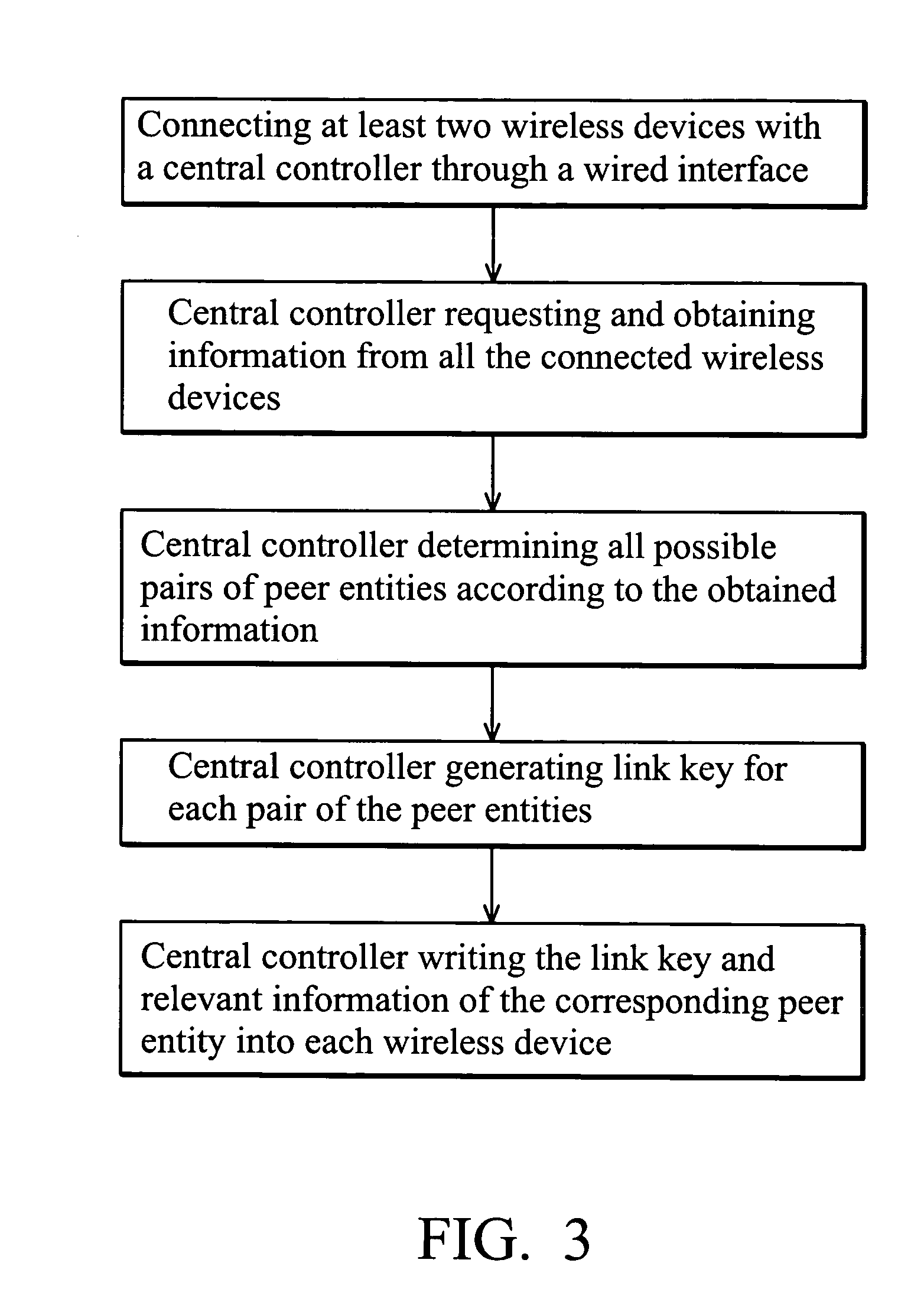
The present invention provides a wireless pairing method that allows for the exchange of relevant information between wireless devices without needing to input numbers or letters. It also allows for the use of a wired interface to connect the wireless devices, making it easier for devices that cannot input numbers to participate in wireless pairing. The central controller detects the wireless devices and reads relevant information about them, such as device type and connection mode. It then generates a dedicated link key for each pair of wireless devices and sends it to each device individually. The wired secure channel between the wireless devices and the central controller ensures secure communication. The central controller can adjust the wireless pairing rules based on different applications. The wireless devices are disconnected from the central controller after completing the pairing procedure. The authentication process uses the assigned Link key to generate an encryption key for data encryption during transmission.

Problems solved by technology

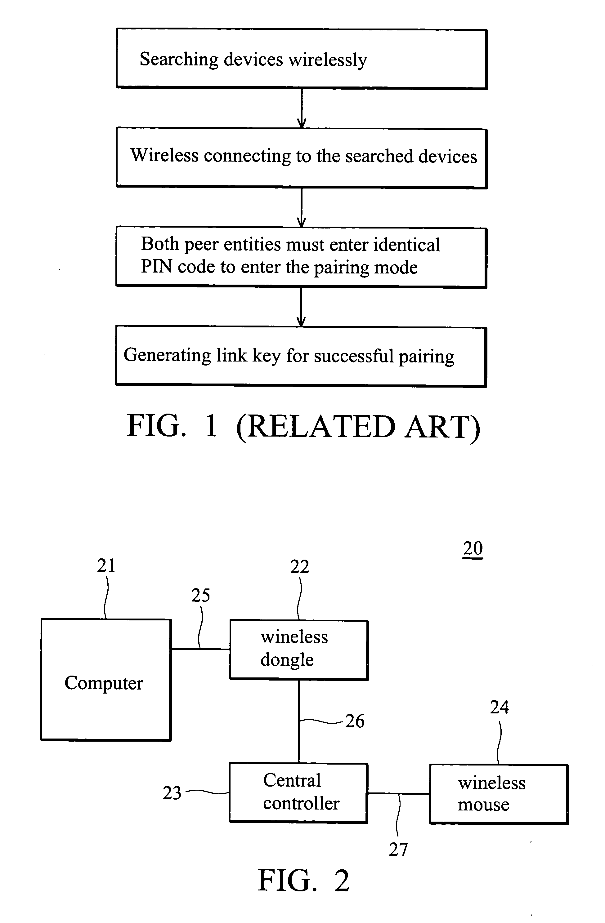
Certain wireless devices, however, are too small in size, or do not have an alphanumeric input interface (such as a wireless mouse or a wireless printer), thus either an added input interface required for supporting enter PIN code during a pairing procedure will cause additional cost, or the wireless devices cannot obtain a Link Key during the wireless pairing procedure and the Encryption Key cannot be generated.
Otherwise, suffer lower security level using fixed PIN code.
Furthermore, errors and problems may occur during the wireless pairing procedure when several similar wireless devices using short range radio communication are located in the same region.

Method used


Image

  • Method and system for wireless pairing
  • Method and system for wireless pairing
  • Method and system for wireless pairing

Examples


Embodiment Construction

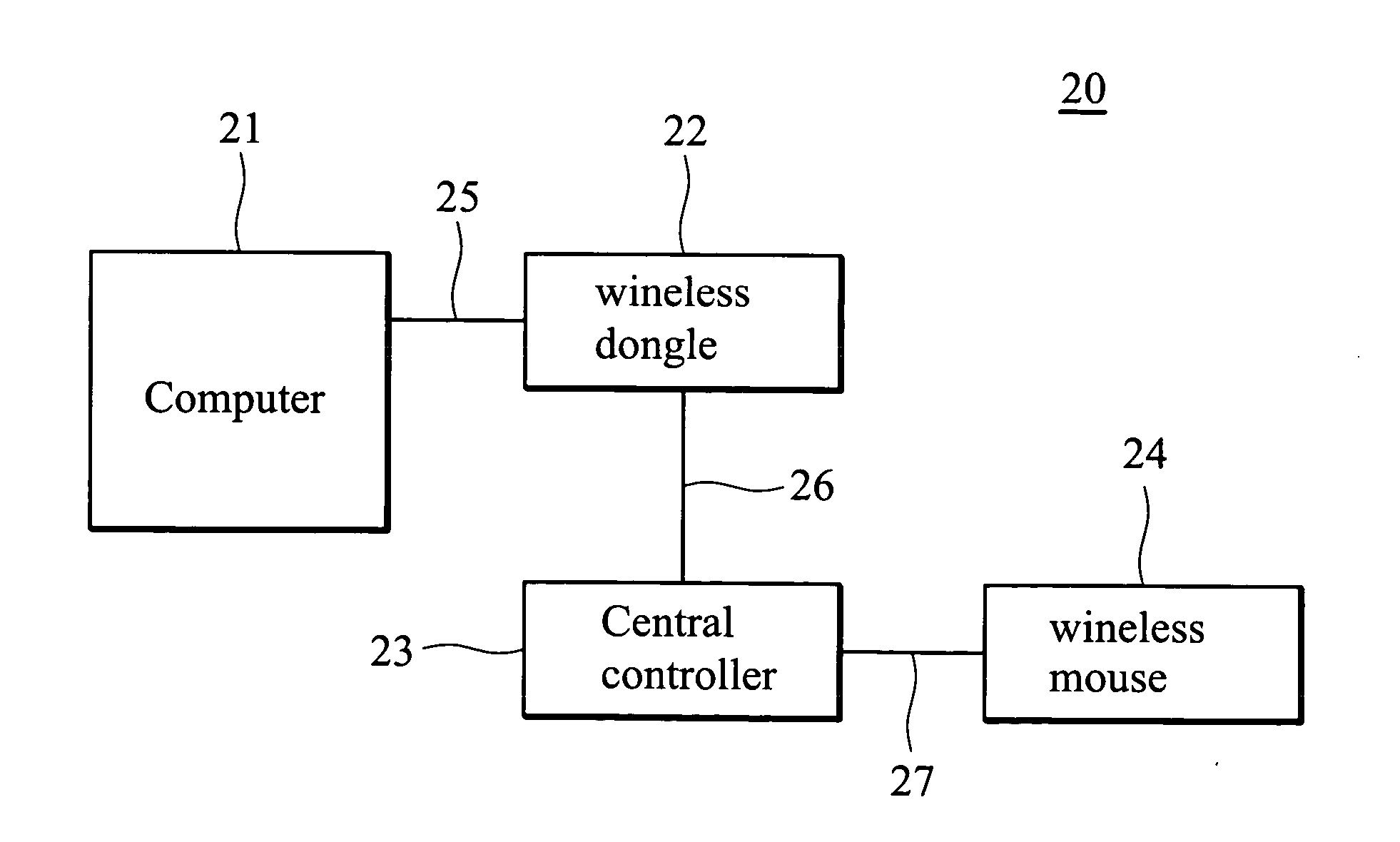
[0023]FIG. 2 illustrates the wireless pairing system 20 using a wired interface according to the embodiment of the present invention. FIG. 2 shows a wireless mouse 24 pairing with a wireless dongle 22. The wireless dongle 22 is connected to a computer 21 through a link 25, such as a universal serial bus (USB), a serial port, for example, an RS-232 port, or an interface supported by the wireless dongle 22, such as PCMCIA (Personal Computer Memory Card International Association). The central controller 23 can be installed in the wireless devices, charger, or computer, whereas the central controller 23 in FIG. 2 is an independent operating system. The central controller 23 in the embodiment is connected to the wireless dongle 22 and the wireless mouse 24 via an Inter IC Bus (I2C Bus) 26 and 27 respectively. The I2C Bus accesses and controls memory directly and does not require extra software and short range radio protocol stack receive commands and transmit responses during the wireles...


PUM


Abstract

A method and system for wireless pairing procedure through a wired interface. The wireless pairing system of the present invention comprises at least two wireless devices and a central controller. First, the wireless devices are connected to the central controller through a wired interface for pairing. The central controller then requests relevant information such as device address, device type, and connection mode of each wireless device. The central controller determines all possible pairs of peer entities according to the relevant information of the wireless devices, and generates a dedicated link key for each pair for successful pairing. Finally, the central controller writes the link key and the relevant information of the corresponding peer entity into each wireless device.

Description

BACKGROUND OF THE INVENTION [0001] 1. Field of the Invention [0002] The present invention relates to a pairing procedure for wireless communication technique, and more specifically, to a method and system thereof for wireless pairing procedure through a wired interface. [0003] 2. Description of the Related Art [0004] Wireless communication, such as blue teeth, between devices such as desktops, notebooks, Personal Digital Assistants (PDA), mobile phones, printers, scanners, digital cameras, and various home electronic appliances is often achieved by short range radio technology. Each wireless device is assigned a unique standard address, in order to establish peer-to-peer, or-peer-to-many low-power wireless connections for a local network. Transmitted data is encrypted and encoded by security procedures before transmission. The security procedure comprises: [0005] 1. PIN (Personal Identification Number) code comparison; [0006] 2. link key pairing; [0007] 3. authentication; [0008] 4. ...

Claims


Application Information

Patent Timeline
Patent Type & Authority Applications(United States)
IPC IPC(8): H04M1/72412H04B7/00H04L9/28
CPCH04M1/7253H04M1/72412
Inventor YU, ROBERTYEH, VANCE
Owner VIA TECH INC
Learn More