Device for the protection of a probe joined to an external wall of an aircraft

a technology for aircraft and probes, applied in the direction of instruments, heat measurement, transportation and packaging, etc., can solve the problems of affecting the safety of the probe, the inability to measure parameters, and the risk of their melting on the prob

Inactive Publication Date: 2005-07-14
AIRBUS OPERATIONS (SAS)
View PDF11 Cites 4 Cited by
  • Summary
  • Abstract
  • Description
  • Claims
  • Application Information

AI Technical Summary

Benefits of technology

[0015] The temperature around the probe increases when the probe is supplied with electrical current. Generally, the probe is supplied with electrical current as soon as an engine of the aircraft has started up. Thus, by making the automatic removal of the protection devices depend on an increase in the ambient temperature of the probes that they protect, it will be ensured that all the protective covers are removed at an early stage in the starting-up of the aircraft. Thus, there is no risk of any overlooked protective cover melting on a probe.
[0020] The deformation temperature depends on the constituent elements of the alloy used to make the fastener means. For example, it is possible to add another constituent material such as iron, chrome, manganese or aluminum to a titanium-nickel alloy. Thus, the deformation temperature of the shape memory material is reduced. This means that the threshold temperature at which the protective cover gets automatically detached from the aircraft wall is reduced. Conversely, gold or palladium can be added to the nickel-titanium alloy in order to increase the deformation temperature of said alloy. The latter approach is particularly valuable when the aircraft are parked in places where the ground temperature is high. Indeed, in this way, the detachment of the protective covers from the wall is prevented when no take-off is planned for the aircraft. In another example, the shape memory material used may be a copper alloy that costs less than nickel-titanium alloy.
[0026] In another exemplary embodiment of the invention, the fastener means are each formed by a through-hole part, capable of crossing the wall, and a holding part that is independent of the through-hole part. During a mounting of the protection, the through-hole part is introduced into a hole of the wall. Then, the through-hole part is held in position by means of a holding part. For example, each through-hole part is provided, at the position of an end designed to cross the wall of the aircraft, with a housing capable of receiving a holding part. The holding part is introduced into the housing and maintains said through-hole part in the hole. For example, the holding part, once positioned in the housing, can extend in a direction perpendicular to the through-hole part. The holding part then comes into contact with an internal face of the wall of the aircraft, and prevents the through-hole part from sliding in the hole.
[0030] In order to prevent breakage of the protective cover when it falls to the ground, it is possible to make the protective cover out of a material, such as plastic, that is resistant to impact. Furthermore, when the fastener means comprise at least one part designed to go through the wall of the aircraft, it is possible to make the fastener means out of metal. Thus, the risk of wear and tear of these fastener means is reduced.
[0039] In any case, it can be planned that the protection device will be capable of being mounted on and dismounted from the wall manually, or more generally mechanically. The sensitivity to heat of the one or more fastener means then makes it possible to cope with any oversight involving one or more protection devices on the wall.

Problems solved by technology

If the protective covers are not removed, the probes cannot be in contact with the exterior elements, and therefore cannot measure the parameters.
Take-off is then generally impossible or dangerous because the information provided by the probe is then erroneous.
The temperature of the probes can then rise to above 200° C. If the protective covers are not removed, there is a risk of their melting on the probes, and thus irretrievably damaging them.
At present, since the protective covers are removed by hand, it is possible that certain protective covers may be overlooked on the wall of the aircraft and cause the above-mentioned damage.

Method used


Image

  • Device for the protection of a probe joined to an external wall of an aircraft
  • Device for the protection of a probe joined to an external wall of an aircraft
  • Device for the protection of a probe joined to an external wall of an aircraft

Examples


Embodiment Construction

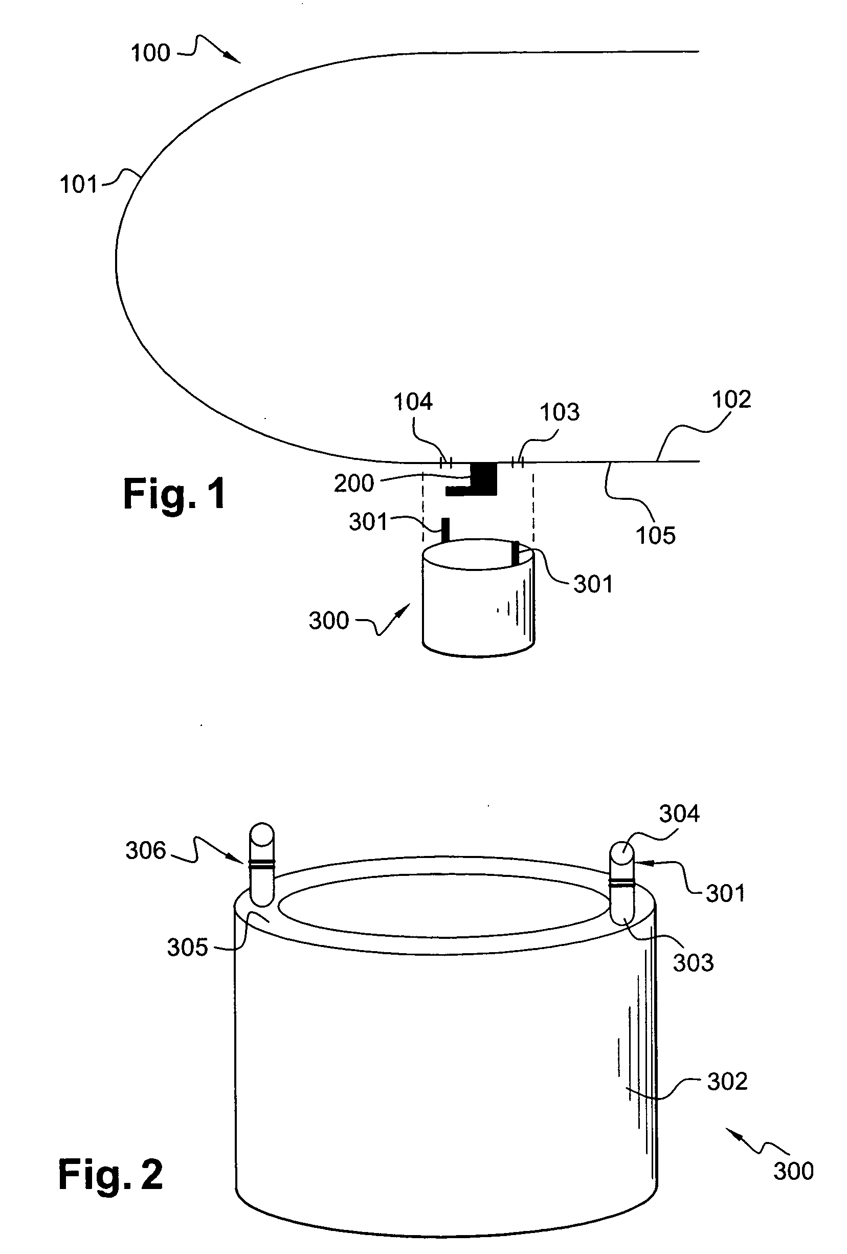
[0045]FIG. 1 is a diagrammatic view of a head 101 of an aircraft 100. A wall 102 of the aircraft 100 carries a probe 200 on an external face 105. The term “external face” is understood to mean the face located outside the aircraft 100. The wall 102 of the aircraft 100 is provided with two holes 103 and 104, on either side of the probe 200. The holes 103 and 104 are capable of receiving fastener means 301 of a device 300 for the protection of the probe 200.

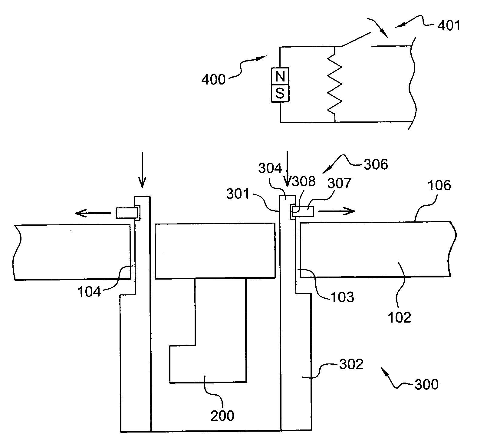
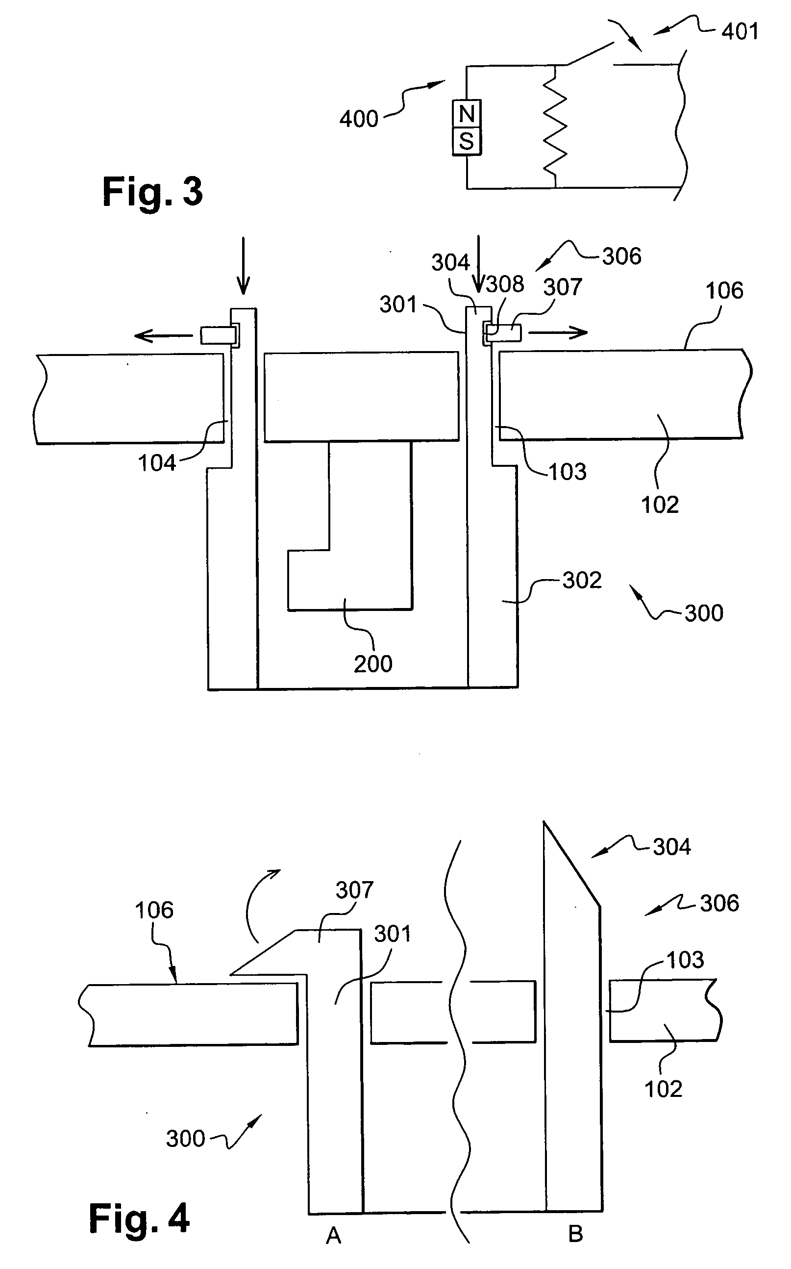
[0046]FIG. 2 shows a more detailed review of the protection device 300. The protection device 300 has a body 302. The body 302 herein has a hollow cylindrical circular shape closed at one end. The probe 200 may be housed in the cylinder 302. The protection device 300 has two fastener means 306. The fastener means 306 are positioned on either side of the body 302. Each fastener means 306 has a through-hole unit 301. A bottom end 303 of the through-hole unit 301 is fixed to a wall 305 of the body 302 coming into contact with the ext...


PUM

PropertyMeasurementUnit
temperatureaaaaaaaaaa

Abstract

The invention relates to a device for the protection of a probe joined to a wall of an aircraft. Detachable means for fastening to the wall of the protection device are sensitive to a modification of a temperature of the probe. For example, the fastening means are made of a shape memory material. A rise in temperature enables a deformation of the fastener means and a separation of the device from the wall. It is also possible to make the fastener means out of magnetostrictive or polarizable material in order to separate the protection device when the fastener means are subjected to a magnetic field. Thus, the fastener means may comprise a polarizable pin that withdraws from a housing made on a through-hole unit when it is subjected to the magnetic field generated by an electromagnet.

Description

RELATED APPLICATION [0001] The present application claims priority to French Application No. 03 51148 filed Dec. 19, 2003. BACKGROUND OF THE INVENTION [0002] 1. Field of the Invention [0003] An object of the invention is a device for the protection of a part joined to a wall. More specifically, an object of the invention is a device for the protection of a probe fixed to an external wall of an aircraft. The protection device is used to isoiate the probe from external phenomena. The invention more particularly relates to detachable means for fastening the device for the protection of said probe to the wall of the aircraft. [0004] It is an aim of the invention to provide a protection device for the temporary and efficient isolation of a probe from exterior elements. It is another aim of the invention to enable an automatic removal of the protection device at an early stage of take-off by the aircraft. [0005] Aircraft are provided with numerous probes positioned on their external wall....

Claims


Application Information

Patent Timeline
Patent Type & Authority Applications(United States)
IPC IPC(8): B64F1/00G01D11/24G01D11/30G01P1/02G01P5/165
CPCB64F1/005G01P5/165G01P1/02
Inventor D'OUINCE, ARNAUDBRIVET, VALERIE
Owner AIRBUS OPERATIONS (SAS)
Why Eureka
Try Eureka