High resolution ct scanner

a technology of ct scanner and high resolution, which is applied in the field of computerized tomography (ct) xray imaging, can solve the problems of inacceptable level of artifacts in images and overly obtrusive images provided by scanners, and achieve the effect of improving image resolution

Inactive Publication Date: 2005-07-14
KONINKLIJKE PHILIPS ELECTRONICS NV
View PDF4 Cites 9 Cited by
  • Summary
  • Abstract
  • Description
  • Claims
  • Application Information

AI Technical Summary

Benefits of technology

[0020] An aspect of some embodiments of the present invention relates to providin

Problems solved by technology

As a result, for a multislice scanner having a cone beam characterized by a large cone angle data processing schemes conventionally used for processing data from single slice scanners or from small cone angle multislice scanners may introduce overly obtrusive artifacts in images provided by the scanners.

Method used


Image

  • High resolution ct scanner
  • High resolution ct scanner
  • High resolution ct scanner

Examples


Embodiment Construction

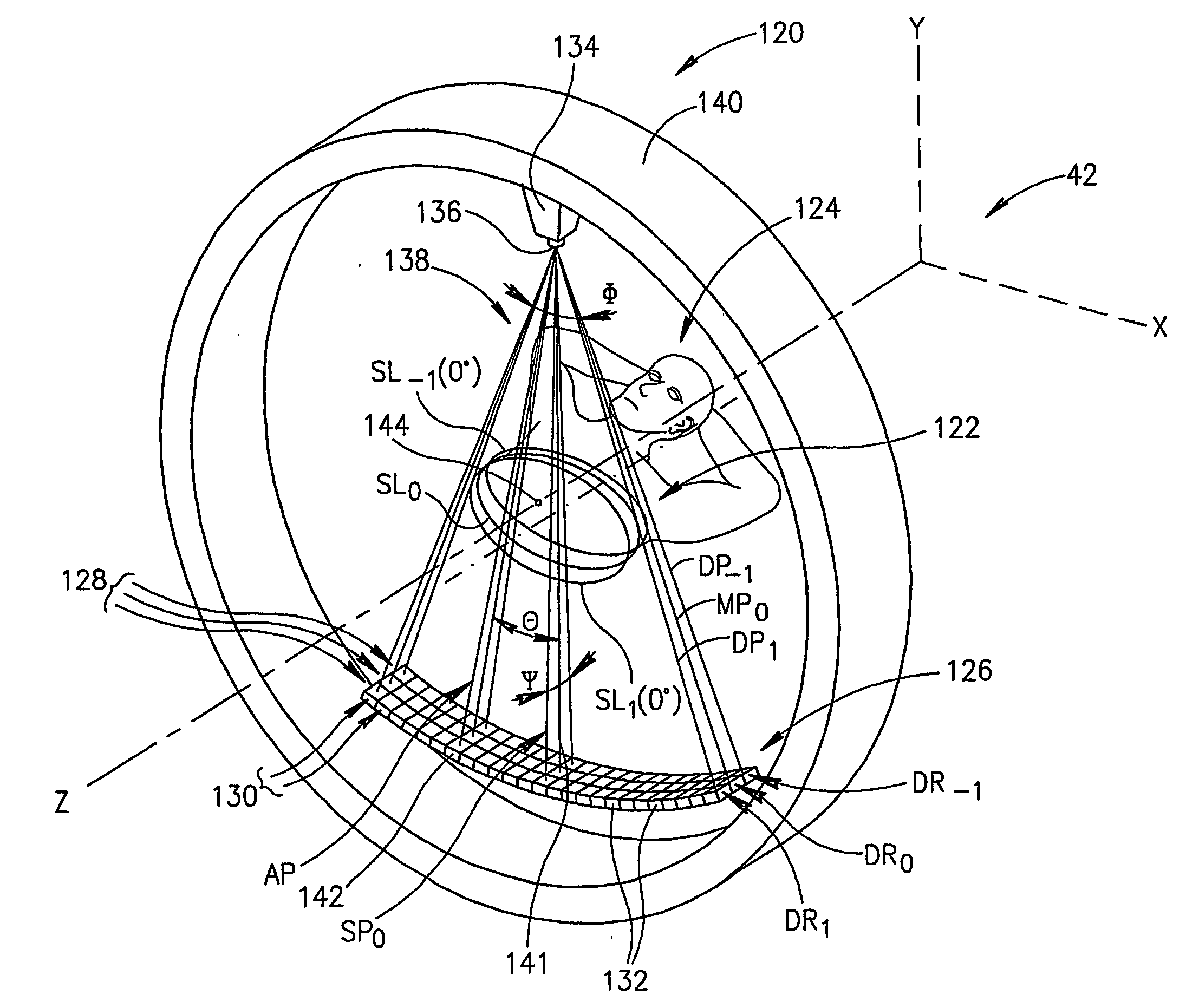
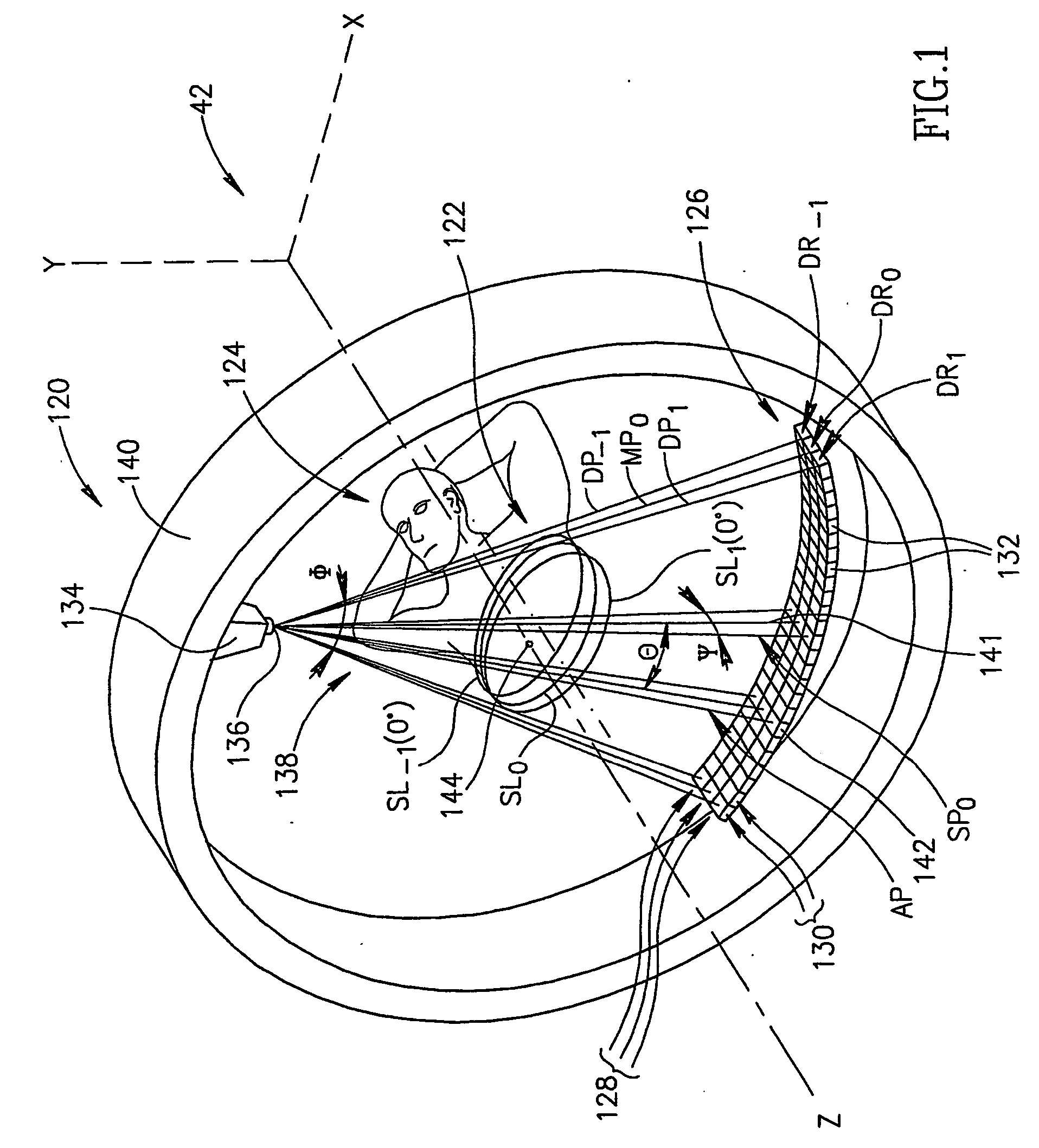
[0065]FIG. 1 schematically shows a third generation multislice CT scanner 120 imaging a region 122 of a patient 124. Only features of multislice scanner 120 germane to the discussion are shown in FIG. 1 and only a portion of patient 124 is shown so that features germane to the discussion are clearly visible.

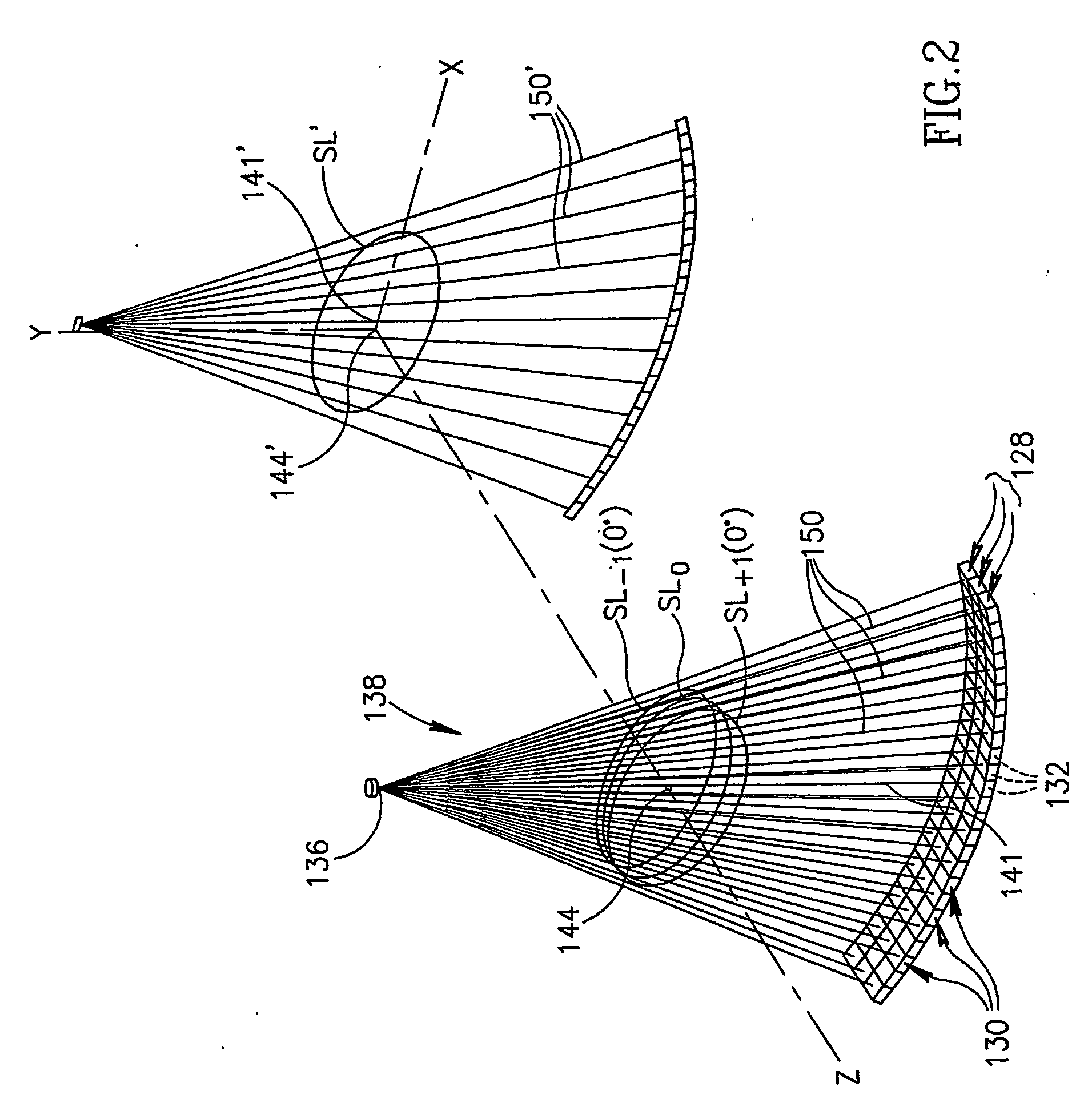
[0066] Multislice scanner 120 comprises a detector array 126 having rows 128 and columns 130 of X-ray detectors 132 and an X-ray source 134 having a focal spot 136 that provides a cone beam 138 of X-rays for illuminating region 122 of patient 124. X-ray source 134 and detector array are mounted to a rotor 140 of a gantry (not shown) comprised in multislice scanner 120. Rotor 140 is rotatable around the z-axis of a coordinate system 42. By way of example, detector array 126 is shown comprising three rows 128 of detectors 132, which rows are individualized by labels DR0, DR1 and DR−1. Patient 124 is supported on a couch (not shown) during imaging of the patient. The couch is contr...


PUM


Abstract

CT scanner is disclosed for providing an image of a region comprising: at least one X-ray cone beam for illuminating mthe region with X-rays; a plurality of rows of X-ray detectors that generate signals responsive to line attenuation of X-rays from the at least one controller that controls providing an image of a region comprising: at least one X-ray cone beam for illuminating the region with X-rays; a plurality of rows of X-ray detectors that generate signals responsive to line attenuation of X-rays from the at least one X-ray source that pass through the region; a controller that controls the at least one X-ray cone beam to acquire line attenuation data for the region for different view angles of the region; and a processor that receives the signals and: a) determines low spatial frequency components of the image from the data; b) generates a first spatial image of the region from the low high spatial frequency components of the image from the data; d) generates a second spatial image of the region from the high frequency components; and e) combines the first and second images to generate the image.

Description

FIELD OF THE INVENTION [0001] The present invention relates to computerized tomography (CT) X-ray imaging and in particular to methods for generating high-resolution CT images. BACKGROUND OF THE INVENTION [0002] In CT X-ray imaging of a patient, X-rays are used to image internal structure and features of a region of the patients body. The imaging is performed by a CT-imaging system, hereinafter referred to as a “CT scanner”, which generally comprises an X-ray source and an array of closely spaced X-ray detectors positioned to face the X-ray source. The X-ray source and array of detectors are mounted in a gantry so that a person being imaged with the CT scanner, generally lying on an appropriate support couch, can be positioned within the gantry between the X-ray source and the array of detectors. The gantry and couch are moveable relative to each other so that the X-ray source and detector array can be positioned axially, along a “z-axis”, at desired locations along the patient's bo...

Claims


Application Information

Patent Timeline
IPC IPC(8): A61B6/03G06T11/00
CPCA61B6/032A61B6/4085Y10S378/901A61B6/027G06T11/006
Inventor SHECHTER, GILAD
Owner KONINKLIJKE PHILIPS ELECTRONICS NV
Why Eureka
Try Eureka