System and method for a GPS enabled antenna

a technology of gps and enabled antennas, applied in the field of system and method of gps enabled antennas, can solve the problems of difficult integration of gps technology with other mobile wireless communication devices such as cellular or personal communications services (pcs) phones, and inconvenient carrying of conventional gps devices with a multitude of mobile wireless communication devices such as laptops, mobile phones, pdas,

Inactive Publication Date: 2005-07-14
KYOCERA CORP
View PDF9 Cites 12 Cited by
  • Summary
  • Abstract
  • Description
  • Claims
  • Application Information

AI Technical Summary

Benefits of technology

[0010] In an exemplary embodiment, the present invention provides a system and a method for providing a GPS enabled antenna for a wireless communications device, such as a wireless handset. The wireless communications device includes a GPS switching module coupled to a conventional communications antenna, including its associated circuitry. The GPS switching module is adapted to selectively couple the communications antenna to GPS matching circuitry. In this arrangement, the GPS matching circuitry adjusts impedance at approximately 1575 MHz to more closely match the communications antenna to GPS circuitry in the wireless device, thus ensuring an optimal transfer of antenna signal energy to the GPS receiver.
[0013] Advantageously, the present invention enables an existing antenna in a wireless communications device to be adapted to robustly receive GPS band signals. Using the existing communications antenna to provide a GPS signal is a cost effective and efficient way to provide GPS position location functionality in a wireless communications device. Furthermore, phone aesthetics are unaffected as no separate GPS antenna is required. Adapting an existing antenna frees up space within the wireless communications device that otherwise might have been reserved for a separate and internal GPS antenna. In addition, since the existing antenna extends from the wireless communications device, the present invention benefits from improved reception of GPS band signals.

Problems solved by technology

Although such positional information can be quite useful, it is not convenient to carry a conventional GPS device along with a multitude of mobile wireless communications devices such as laptops, mobile phones, PDAs, or other mobile devices on which users now depend.
Unfortunately, the integration of GPS technology with other mobile wireless communications devices such as, for example, cellular or personal communications services (PCS) phones has proven difficult.
In particular, three alternatives have been identified for adding GPS capability to a wireless device or handset, but have proven unsatisfactory in use.
However, as mobile handsets for wireless networks have become much smaller, less space is available on the handset housing to accommodate a separate, custom-designed GPS antenna.
Furthermore, a GPS antenna disposed within the handset housing typically suffers from a number of reception problems.
For example, poor reception can be caused by electromagnetic shielding within the handset housing and by the handset housing itself.
Adjusting the electromagnetic shielding to accommodate the GPS antenna may cause substantial redesign and testing of the handset.
Even the hand of the user of the wireless handset may interfere with the reception by the internal GPS antenna as the user grips the handset housing.
Also, adding a separate antenna and its associated circuitry to the wireless handset adds expense and design complexity.
However, the GPS signal is at a non-resonant frequency for the dual-band antenna, so the received GPS signal would be less than optimal resulting in degraded signal transfer.
In this regard, known dual-band antenna systems are not able to receive a GPS signal with sufficient strength and quality to implement a robust GPS location functionality on a wireless handset.
Although such an antenna enables the GPS signal to be received, due to the limitations of antenna design such an antenna normally compromises either the cellular or PCS performance, or both.
Using a tri-band antenna also substantially adds extra cost to the antenna.

Method used


Image

  • System and method for a GPS enabled antenna
  • System and method for a GPS enabled antenna
  • System and method for a GPS enabled antenna

Examples


Embodiment Construction

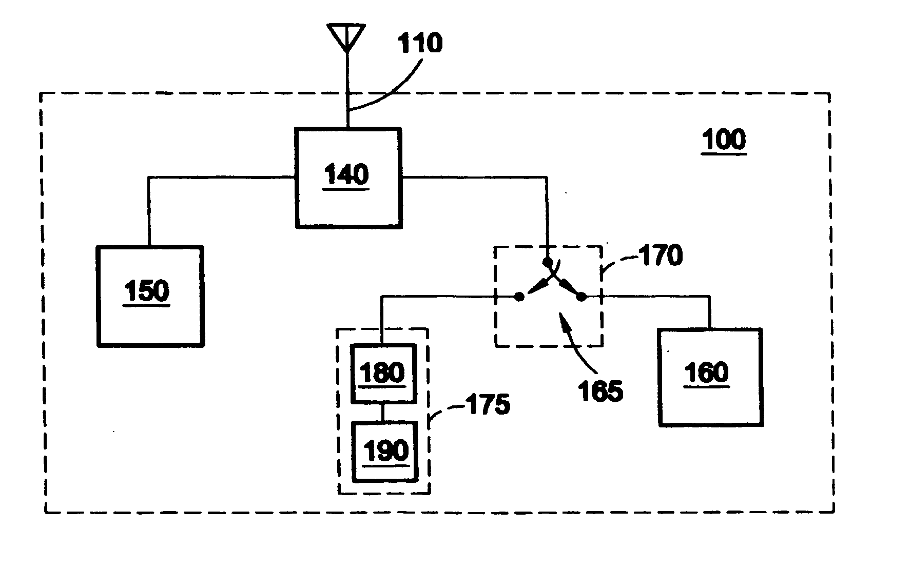
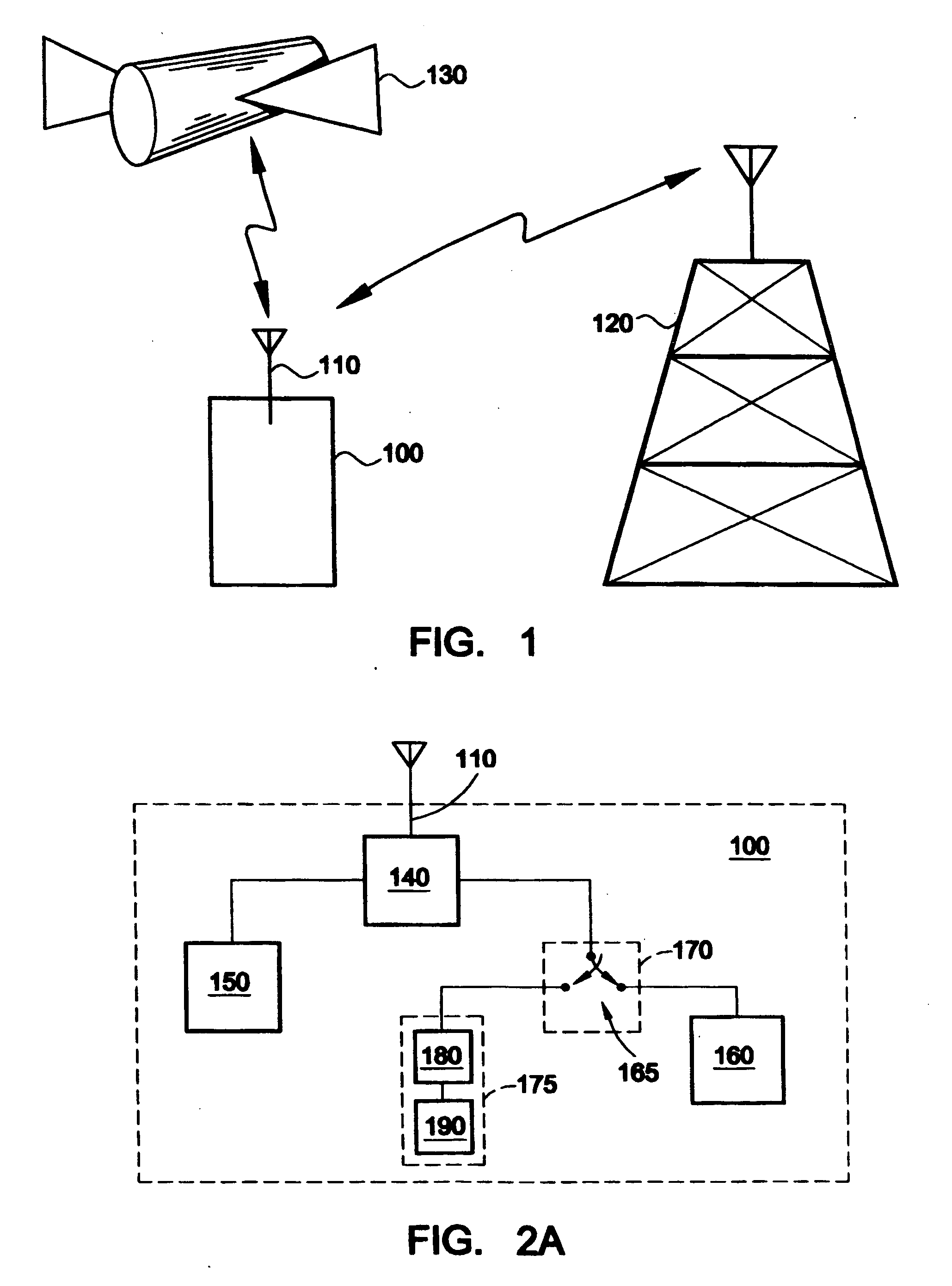
[0026]FIG. 1 illustrates an exemplary embodiment of a wireless communications system including a wireless communications device 100 according to the present invention. The wireless communications device 100 may include, for example, a handheld wireless communications device, a mobile phone, a car phone, a cellular or a personal communications services (PCS) phone, a cordless phone, a laptop computer or other computing device with a wireless modem, a pager, or a personal digital assistant (PDA). The wireless device 100 may be digital or analog or some combination thereof. Indeed, the present invention contemplates other forms of wireless communications devices known to one of ordinary skill in the art.

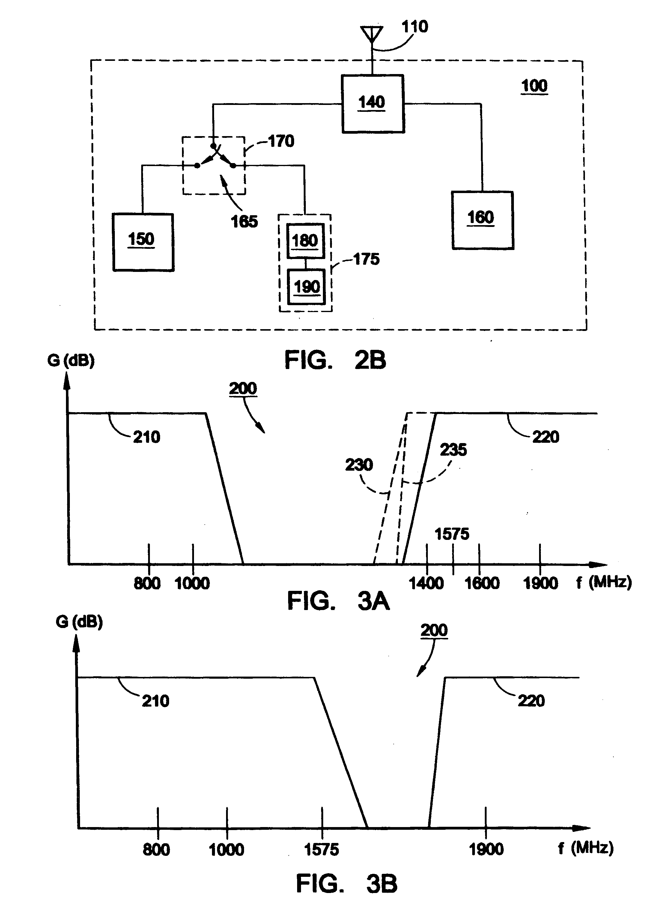
[0027] The wireless communications device 100 includes an antenna 110. The antenna 110 is structured to transmit and receive wireless communications signals. In FIG. 1, the antenna 110 is in two-way communications with a base station 120. The base station 120 may be, for example, one o...


PUM


Abstract

A system and method for providing a global positioning system (GPS) enabled antenna system are provided. The GPS enabled antenna may be used, for example, on a wireless communications device such as a wireless handset. The wirelesscommunications device includes a GPS switching module coupled to a conventional communications antenna, including its associated circuitry. The GPS switching module is adapted to selectively couple the communications antenna to GPS matching circuitry. In this arrangement, the GPS matching circuitry adjusts impedance at approximately 1575 MHz to more closely match the communications antenna to GPS circuitry in the wireless device.

Description

RELATED APPLICATIONS [0001] This is a continuation application of U.S. application Ser. No. 09 / 898,269, filed on Jul. 3, 2001, which is hereby incorporated by reference.FIELD OF THE INVENTION [0002] The present invention generally relates to a system and a method for providing a global positioning system (GPS) enabled antenna. BACKGROUND OF THE INVENTION [0003] A conventional hand-held global positioning system (GPS) device provides positional information about the location of the GPS device by receiving and processing GPS band signals from a GPS system including satellites and base stations. Although such positional information can be quite useful, it is not convenient to carry a conventional GPS device along with a multitude of mobile wireless communications devices such as laptops, mobile phones, PDAs, or other mobile devices on which users now depend. It is therefore desirable that a GPS positioning function be included with another device, such as a wireless mobile handset. [00...

Claims


Application Information

Patent Timeline
Patent Type & Authority Applications(United States)
IPC IPC(8): G01S1/00G01S19/36H04B1/18H04B1/38H04B1/40H04B1/44
CPCG01S19/36H04B1/44H04B1/3805H04B1/50
Inventor FORRESTER, TIMOTHY DAVID
Owner KYOCERA CORP
Why Eureka
Try Eureka