Device for measuring electrocardiogram with tapeless format and its method

Inactive Publication Date: 2005-07-14
LIN KANG PING
21 Cites 11 Cited by

AI-Extracted Technical Summary

Problems solved by technology

If the patient have the symptom with fever caused by sickness, the patient would be uncomfortable while taking off sleeves, pants, smearing o...

Abstract

The present invention is in relative to a a device for measuring electrocardiogram with tapeless format and its method, especially the electrocardiogram measure device which measures electrocardiogram signals via electrodes with flat shape touching with two roots between total four fingers of two hands or electrodes embedded-in thereon only touching with two fingers for two hands, the invention can display the electrocardiogram measured directly without adding any conductive material. The present invention comprises a shell, shaped as a thin and long cube and having at least one operating panel, the operating panel further comprising at least one button for setting and transferring functions; at least two gelless electrodes with thin foil shape, slightly embedded and fixed in the operating panel and extended and surrounded at least one edge of the shell to a surface opposite to the operating panel; at least one information display, located on the operating panel to display a plurality of measured values; a calculation system, connecting with two gelless electrodes and the information display located in the shell in order to calculate relative electrical information measured from the gelless electrodes and display results on the information display.

Application Domain

ElectrocardiographySensors

Technology Topic

ElectricityElectrocardiogram measures +7

Image

  • Device for measuring electrocardiogram with tapeless format and its method
  • Device for measuring electrocardiogram with tapeless format and its method
  • Device for measuring electrocardiogram with tapeless format and its method

Examples

  • Experimental program(1)

Example

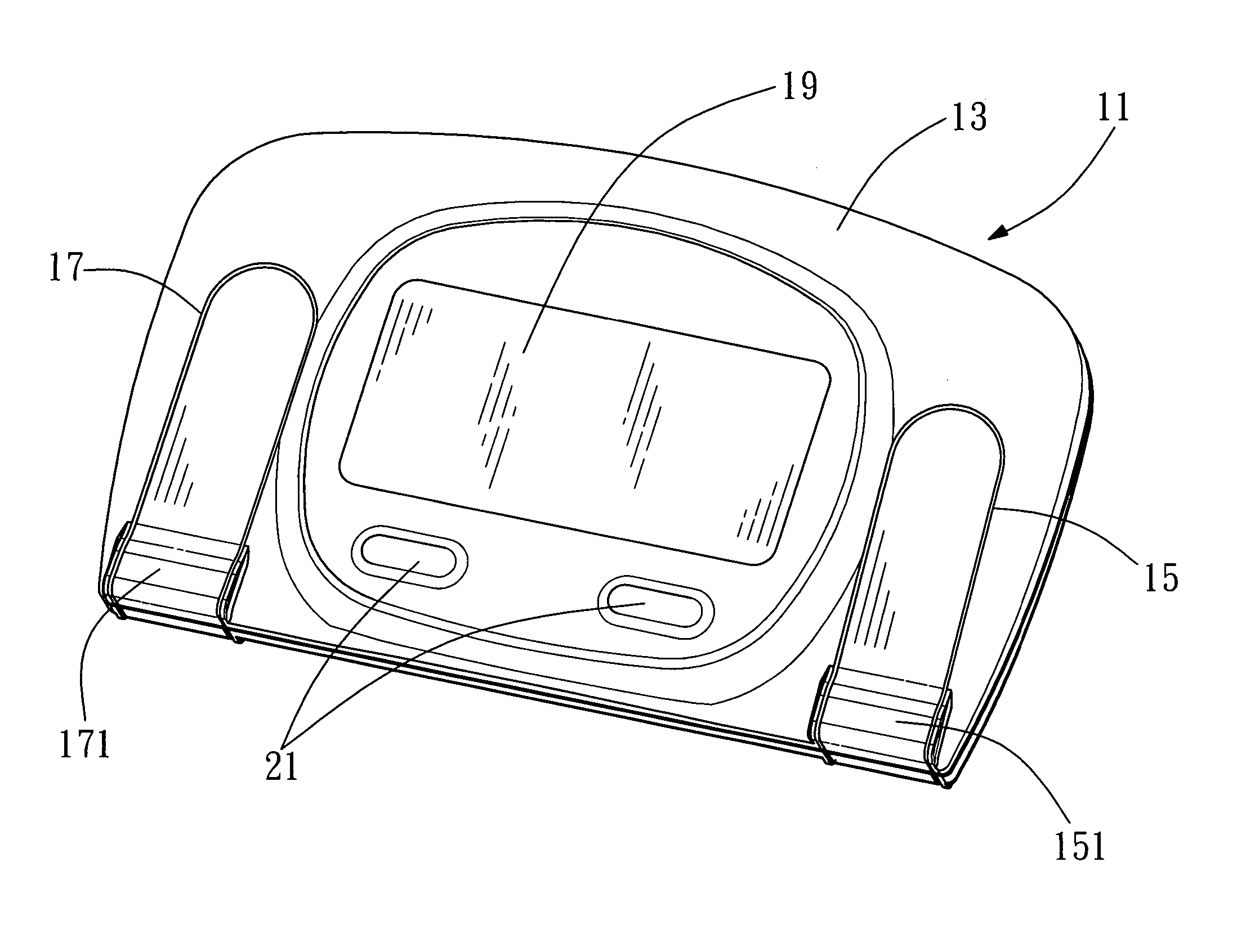
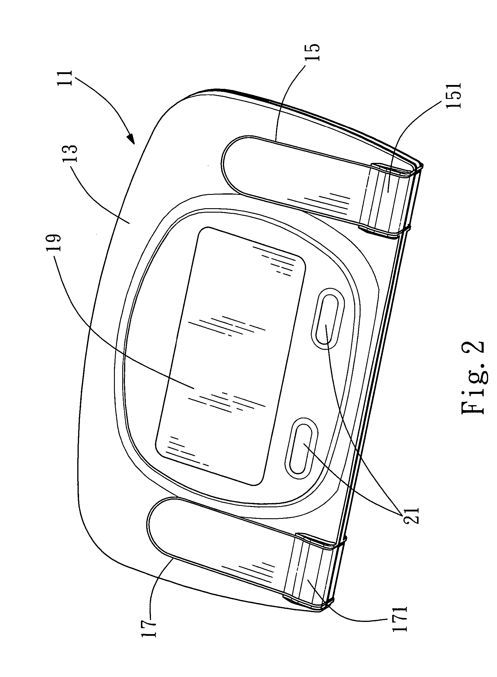
[0017] Please refer to FIG. 2 and FIG. 3, which are a 3-D sketch of a front view and a 3-D sketch of a rear view of the preferred embodiment of the present invent. The present invention comprises a shell 11, shaped as a thin and long cube and having an operating panel 13, the operating panel 13 further comprising two buttons 21 for setting and transferring functions; two gelless electrodes with thin foil shape, a right and a left electrodes 15, 17, slightly embedded and fixed in the operating panel 13 and extended and surrounded an edge of the shell 11 to a bottom surface 23 opposite to the operating panel 13, electrodes 15 and 17 being made by any conductive metal or conductive rubber, further, both places of electrodes 15 and 17 surrounding the edge of the shell 11 individually having protruding surfaces or ridges 151 and 171 for helping two roots of four fingers of two hands to clamp closely; an information display 19, located on the operating panel 13 to display a plurality of measured values; a calculation system 27 (not shown on FIG. 2 and FIG. 3), connecting with electrodes 15 and 17 and the information display 19 located in the shell 11 in order to calculate relative electrical information measured from the electrodes 15 and 17 and displaying the measured values on the information display 19.
[0018] Please refer to FIG. 4, which is a structural sketch of hardware of the calculation system of the present invention. FIG. 4 discloses a relationship among all main components in the calculation system 27 and another relationship among the calculation system 27, electrodes 15 and 17 and information display 19. The calculation system 27 comprises a pre-signal amplify circuit 271, an electrocardio signal amplify/filter circuit 273, an analog/digital converting circuit 275 and a CPU 277. Arrows shown in FIG. 4 are the process for calculation, it means the pre-signal amplify circuit 271 amplifies signals of received electrical information and constantly the electrocardio signal amplify/filter circuit 273, the analog/digital converter circuit 275 and the CPU 277 execute calculation when right and left electrodes 1517 receiving relative electrical information. Wherein, a loop is formed by electrocardio signal amplify/filter circuit 273, analog/digital converter circuit 275 and CPU 277, whose main function is to process different information values including ST segment, QRS interval and heartbeat rate. At last, these information values are shown on the display 19.
[0019] Please refer to FIG. 5, which is a flowchart of measuring steps of the present invention. The steps include: [0020] (1) to start a tapeless electrocardiogram measuring device; [0021] (2) to collect relative electrical data via two roots within total four fingers of two hands touching two gelless electrodes of an operating panel of the tapeless electrocardiogram measuring device, the gelless electrodes being made by any conductive metal or conductive rubber; [0022] (3) to identify quality for the relative electrical data, if unacceptable, then returning to step (2), otherwise going to next step; [0023] (4) to electrically calculate the relative electrical data with a calculation system, comprising a pre-signal amplify circuit, an electrocardio signal amplify/filter circuit, an analog/digital transfer circuit and a CPU, within the tapeless electrocardiogram measuring device for detecting QRS interval; [0024] (5) the calculation system executing ST segment; [0025] (6) the calculation system judging arrhythimia; [0026] (7) to present a plurality of information values, as a ST segment, a QRS interval and a heartbeat rate, on an information display on the operating panel; [0027] (8) to finish the method.
[0028] Please refer to FIG. 6 and FIG. 7, which are a 3-D sketch of a front view of a second preferred embodiment of the present invent and a 3-D sketch of a rear view of the second preferred embodiment of the present invent. The device for measuring electrocardiogram with tapeless format comprises: a shell 31, shaped as a thin and long cube and having one operating panel 33, the operating panel 33 including three buttons 41 to set and transfer functions; four gelless electrodes, two right electrodes 35, 35′ and two left electrodes 37, 37′ , slightly embedded and fixed in the operating panel 33 and a bottom surface 43, the gelless electrodes being made by any conductive metal or conductive rubber; one information display 39, located on the operating panel 33 to display a plurality of measured values, the plurality of information values shown on the information display 39 including values of ST segment, QRS interval and heart-beat rate; a calculation system (not shown in FIG. 6 and FIG. 7, referring to FIG. 4), connecting with the four gelless electrodes 35, 35′, 37 and 37′ and the information display 39 located in the shell 31 in order to calculate relative electrical information measured from the gelless electrodes 35, 35′, 37 and 37′ and display results on the information display 39, the calculation system further comprising a pre-signal amplify circuit, an electrocardio signal amplify/filter circuit, an analog/digital transfer circuit and a CPU, wherein the pre-signal amplify circuit connected to the gelless electrodes to get relative electrical data, and continuously results being displayed on the information display 39 after calculating the electrical data by means of the electrocardio signal amplify/filter circuit and the analog/digital transfer circuit and the CPU.
[0029] Please refer to FIG. 8, which is a flowchart of measuring steps of the second preferred embodiment of the present invention. The steps include: [0030] (1′)to start a tapeless electrocardiogram measuring device; [0031] (2′)to collect relative electrical data via four finger tips of two hands touching four gelless electrodes of an operating panel of the tapeless electrocardiogram measuring device, the gelless electrodes being made by any conductive metal or conductive rubber; [0032] (3′)to identify quality for the relative electrical data, if unacceptable, then returning to step (2), otherwise going to next step; [0033] (4′)to electrically calculate the relative electrical data with a calculation system, comprising a pre-signal amplify circuit, an electrocardio signal amplify/filter circuit, an analog/digital transfer circuit and a CPU, within the tapeless electrocardiogram measuring device for detecting QRS interval; [0034] (5′)the calculation system executing ST segment; [0035] (6′)the calculation system judging arrhythimia; [0036] (7′)to present a plurality of information values, as a ST segment, a QRS interval and a heartbeat rate, on an information display on the operating panel; [0037] (8′)to finish the method.
[0038] Please refer to FIG. 9, which is a 3-D sketch of a front view of a third preferred embodiment of the present invent. The device for measuring electrocardiogram with tapeless format comprises: a cover 63; a shell 51, shaped as a thin and long cube and having one operating panel 53, the operating panel 53 including three buttons 61 to set and transfer functions; two gelless electrodes 55 and 57, slightly embedded and fixed in the operating panel 53, the gelless electrodes being made by any conductive metal or conductive rubber; one information display 59, located on the operating panel 53 to display a plurality of measured values, the plurality of information values shown on the information display 59 including values of ST segment, QRS interval and heart-beat rate; a calculation system (not shown in FIG. 9, referring to FIG. 4), connecting with the two gelless electrodes 55 and 57 and the information display 59 located in the shell 51 in order to calculate relative electrical information measured from the gelless electrodes 55 and 57 and display results on the information display 59, the calculation system further comprising a pre-signal amplify circuit, an electrocardio signal amplify/filter circuit, an analog/digital transfer circuit and a CPU, wherein the pre-signal amplify circuit connected to the gelless electrodes to get relative electrical data, and continuously results being displayed on the information display 59 after calculating the electrical data by means of the electrocardio signal amplify/filter circuit and the analog/digital transfer circuit and the CPU.
[0039] Please refer to FIG. 10, which is a flowchart of measuring steps of the third preferred embodiment of the present invention. The steps include: [0040] (1″) to start a tapeless electrocardiogram measuring device; [0041] (2″) to collect relative electrical data via two finger tips of two hands touching two gelless electrodes of an operating panel of the tapeless electrocardiogram measuring device, the gelless electrodes being made by any conductive metal or conductive rubber; [0042] (3″) to identify quality for the relative electrical data, if unacceptable, then returning to step (2), otherwise going to next step; [0043] (4″) to electrically calculate the relative electrical data with a calculation system, comprising a pre-signal amplify circuit, an electrocardio signal amplify/filter circuit, an analog/digital transfer circuit and a CPU, within the tapeless electrocardiogram measuring device for detecting QRS interval; [0044] (5″) the calculation system executing ST segment; [0045] (6″) the calculation system judging arrhythimia; [0046] (7″) to present a plurality of information values, as a ST segment, a QRS interval and a heartbeat rate, on an information display on the operating panel; [0047] (8″) to finish the method.
[0048] The device for measuring electrocardiogram with tapeless format as described above can be applied on other electrical products, which can be one of the following: mobile phone, walkie-talkie, portable computer, walkman and the relatives. The main purpose is to let people understand their health right away, therefore any disease for heart or blood vessel can be avoided in advance.
[0049] Known from above description, the present invention adopts a unique measuring method completely different than prior arts to collect the relative electrical data of physiology by touching two thin electrodes with the roots of total four fingers of two hands or electrodes embedded in thereon only touching with two fingers for two hands. Wherein, there is only two thin electrodes without smearing any conductive material on skin or electrodes, and the present invention can be instead of the complex measuring process with pasting the electrodes on hand ankle and chest; on the other hand, the measuring apparatus for the present invention can be purified and lighter due to easier measuring method.
[0050] It is to be understood that while the invention has been described above in conjunction with preferred specific embodiments, the description and examples are intended to illustrate and not limit the scope of the invention, which is defined by the scope of the appended claims.

PUM

no PUM

Description & Claims & Application Information

We can also present the details of the Description, Claims and Application information to help users get a comprehensive understanding of the technical details of the patent, such as background art, summary of invention, brief description of drawings, description of embodiments, and other original content. On the other hand, users can also determine the specific scope of protection of the technology through the list of claims; as well as understand the changes in the life cycle of the technology with the presentation of the patent timeline. Login to view more.
Why Eureka
Try Eureka