
Method for configuring and/or operating an automation device

a technology of automation device and engineering system, applied in the direction of data switching network, program control, instruments, etc., to achieve the effect of reducing the configuration tim

Active Publication Date: 2005-07-14
SIEMENS AG
View PDF5 Cites 4 Cited by
  • Summary
  • Abstract
  • Description
  • Claims
  • Application Information

AI Technical Summary

Benefits of technology

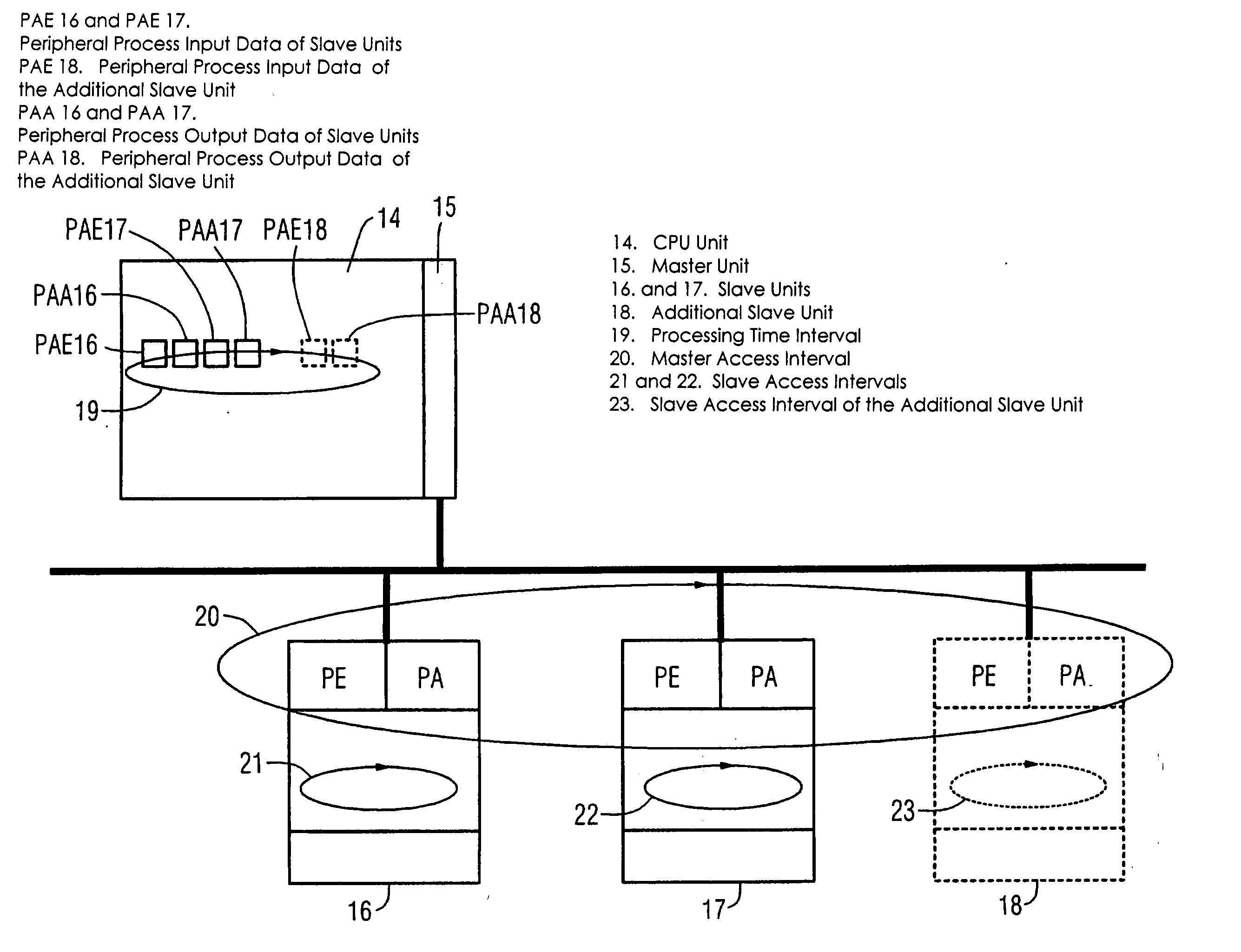
[0010] One object of the present invention is to provide a method for configuring and / or operating an automation device, which reduces the configuration time with respect to a possible expansion of the automation device. A further object of the invention is to provide an engineering system, which makes it possible to carry out the method for configuring the automation device. Yet another object is to provide an automation device that is expandable by one or more additional slave units for a control without reconfiguration with respect to the master access interval and the slave access intervals.

Problems solved by technology

This is time-consuming, particularly because the new configuration must be tested prior to any open loop control operation.

Method used


Image

  • Method for configuring and/or operating an automation device
  • Method for configuring and/or operating an automation device
  • Method for configuring and/or operating an automation device

Examples


Embodiment Construction

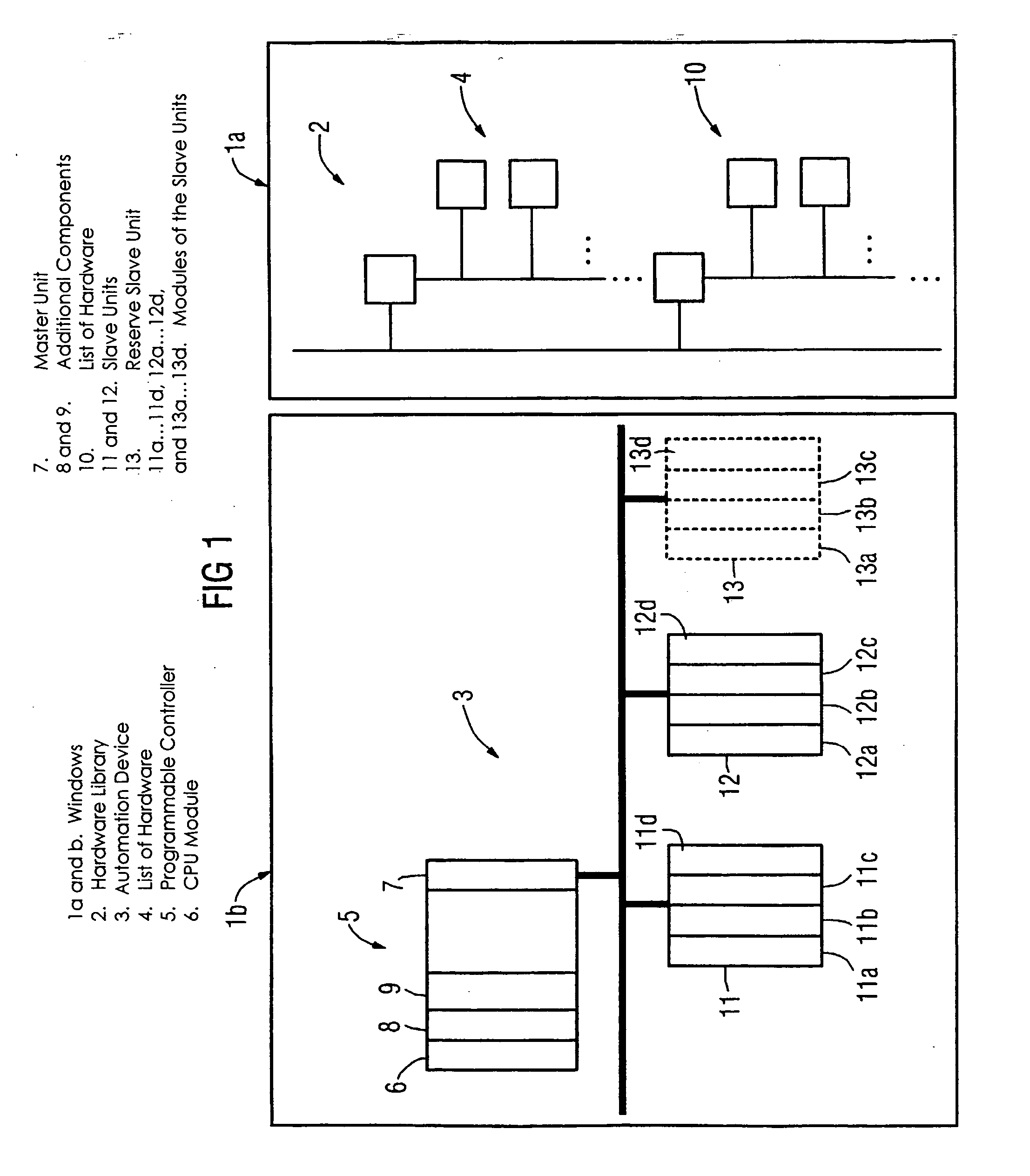
[0019]FIG. 1 shows an engineering system with a display. This display has two windows of a user interface, designated 1a and 1b, respectively. The window 1a is provided to display a hardware library 2 of an automation device, while the window 1b displays the currently configured hardware of an automation device 3. The hardware library 2 contains configuration data for modules of a programmable controller, e.g., CPU modules, communication modules, digital input and / or output modules, and configuration data for modules of peripheral devices and bus systems with associated bus connections. To configure the automation device, an operator uses his mouse in a drag and drop operation to select a hardware component from the window 1a, copy the selected hardware component to the window 1b and combine the components in the window 1b with the copied component in accordance with a control task to be solved.

[0020] In the depicted example, a programmable controller 5 with a CPU module 6, a maste...


PUM


Abstract

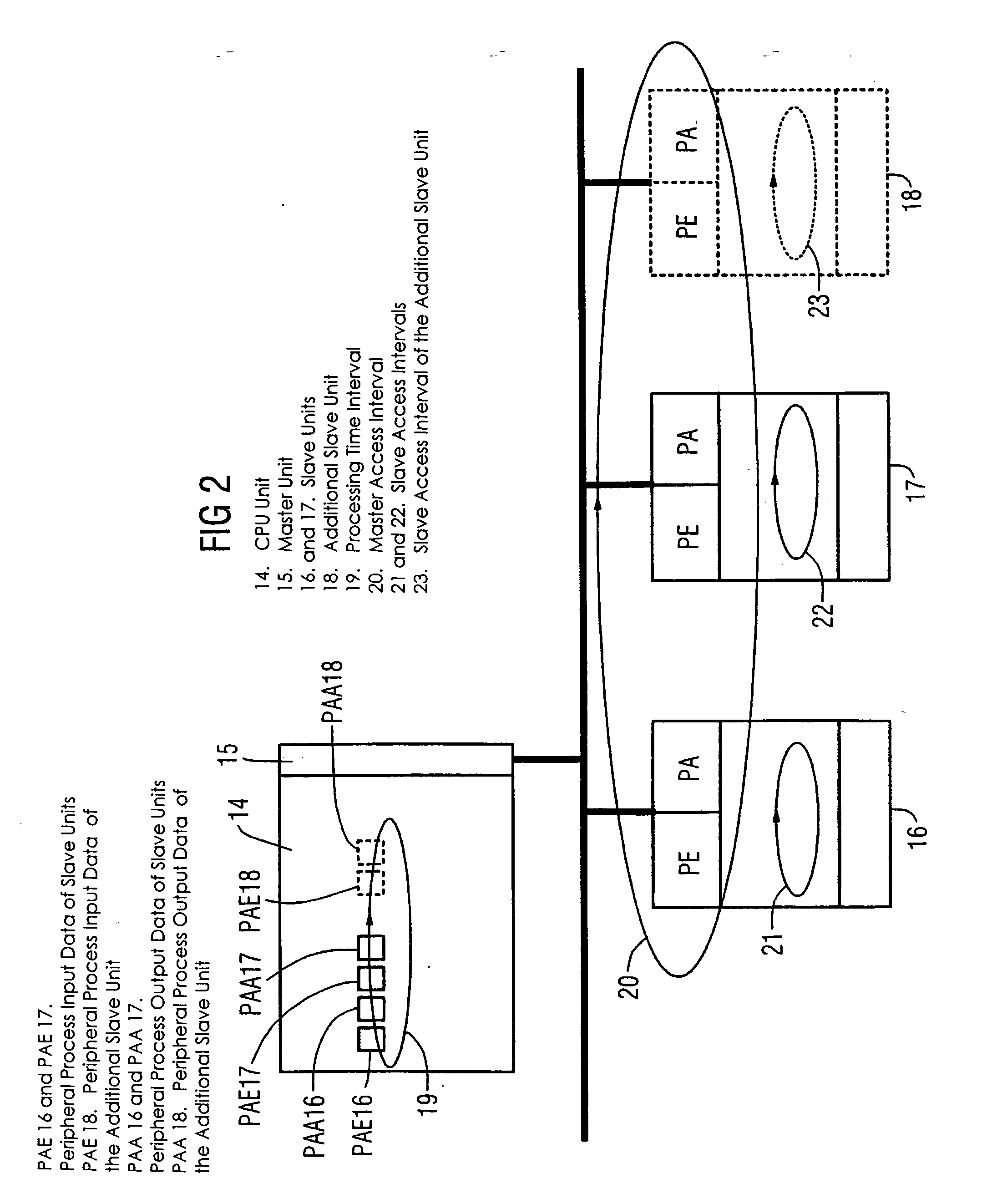
A method and an engineering system that reduce the configuration complexity with regard to a possible expansion of the automation device are provided. The automation device includes slave units and a master unit (7, 15) connected to the slave units via a bus. The slave units include one or more slave units (11, 12, 16, 17) and one or more reserve slave units (13, 18). The configuration of a reserve slave unit (13, 18) enables the master access time interval (20) and the slave access time intervals (21, 22, 23) to be expanded for a possible expansion of the automation device. As a result, a configured automation device of this type can be expanded by an additional slave unit without additional configuration or reconfiguration.

Description

[0001] This is a Continuation of International Application PCT / DE03 / 01137, with an international filing date of Apr. 7, 2003, which was published under PCT Article 21(2) in German, and the disclosure of which is incorporated into this application by reference.FIELD AND BACKGROUND OF THE INVENTION [0002] 1. Field of the Invention [0003] The present invention relates to a method and an engineering system for configuring and / or operating an automation device In particular, the present invention relates to a method and an engineering system for configuring an / or operating an automation device with a master unit and at least one slave unit that can be connected to the master unit via a bus. [0004] 2. Description of Related Art [0005] An automation device with so-called “decentralized peripherals” is known from the Siemens Catalog ST 70, Chapter 6, 2001 Edition, which is incorporated herein by reference. These “decentralized peripherals” are provided for decentralized solutions to automat...

Claims


Application Information

Patent Timeline
Patent Type & Authority Applications(United States)
IPC IPC(8): G05B19/042H04L12/403
CPCG05B19/0421G05B2219/2231H04L2012/4026H04L12/403H04L12/40169
Inventor BECKER, PETERRENSCHLER, ALBERT
Owner SIEMENS AG
Learn More