X-ray tube with housing adapted to receive and hold and electron beam deflector

a technology of electron beam deflector and x-ray tube, which is applied in the direction of x-ray tube electrodes, electrical equipment, electric discharge tubes, etc., can solve the problems of inability to effectively evacuate the yoke, abandon the laminated structure, and cannot be placed inside the evacuated housing, so as to achieve accurate and efficient positioning of the focus on the anode, high effective and efficient deflection of electron beam, and stable structure

Inactive Publication Date: 2005-07-21
SIEMENS AG
View PDF6 Cites 9 Cited by
  • Summary
  • Abstract
  • Description
  • Claims
  • Application Information

AI Technical Summary

Benefits of technology

[0011] The above object is achieved in accordance with the principles of the present invention in a rotating anode X-ray tube having an evacuated housing with a canister-shaped projection in which the cathode is disposed. The canister-shaped projection is in communication with a larger region of the evacuated housing, in which the anode is disposed, with the electron beam proceeding from the cathode through a communicating opening between the canister-shaped projection and the larger volume, and striking the anode (anode dish) in the larger volume. The canister-shaped projection has two parallel tubes proceeding therethrough which are open to the exterior of the canister-shaped projection, but which are sealed fluid-tight with respect to the interior of the canister-shaped projection. The tubes are disposed relatively close together, and the electron beam, during operation of the rotating anode X-ray tube, proceeds between the tubes in the interior of the canister-shaped projection. The legs of a U-shaped electron beam deflector of laminate construction are slid into the respective tubes, so that the deflector is disposed very close to the electron beam, thereby allowing highly effective and efficient deflection of the electron beam, and an associated accurate and efficient positioning of the focus on the anode.
[0012] Because the beam deflector is not disposed in the interior of the evacuated housing, the laminate structure of the beam deflector can still be employed, without imposing evacuation problems. The canister-shaped projection has a mechanically stable structure, and therefore even though the legs of the beam deflector are disposed much closer to the electron beam than in conventional rotating anode X-ray tubes of this type, the mechanical strength of the overall rotating anode X-ray tube is not compromised.

Problems solved by technology

Because of this laminated structure, the yoke cannot be effectively evacuated, and therefore it cannot be placed inside of the evacuated housing of such a rotating anode X-ray tube.
The physical dimensions of the neck region thus impose a minimum distance between the electron beam and the deflector, which cannot be reduced in a conventional rotating anode tube of the type described above, due to the necessity of keeping the deflector at the exterior of the housing.
As noted above, however, the laminate structure serves a beneficial purpose, namely minimizing eddy current losses, and therefore abandoning the laminated structure would be degrade the operation of the deflector.
A fracture of the evacuated housing of the X-ray tube at any location is a serious problem, because not only is the vacuum then destroyed, precluding further operation of the X-ray tube, but also oil contained in the radiator housing can then leak into the interior of the evacuated housing.

Method used


Image

  • X-ray tube with housing adapted to receive and hold and electron beam deflector
  • X-ray tube with housing adapted to receive and hold and electron beam deflector
  • X-ray tube with housing adapted to receive and hold and electron beam deflector

Examples


Embodiment Construction

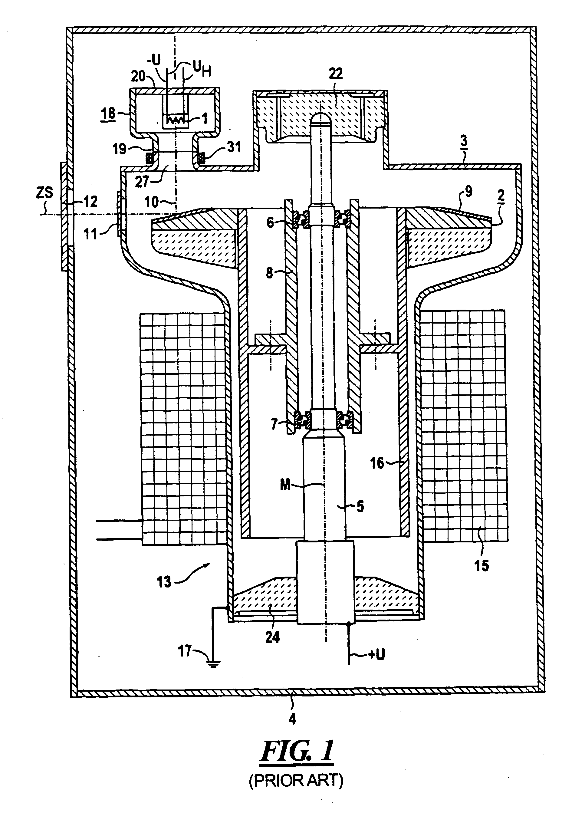
[0021]FIG. 1 is a sectional view through a conventional rotating anode X-ray tube, as described in the aforementioned U.S. Pat. No. 5,909,479.

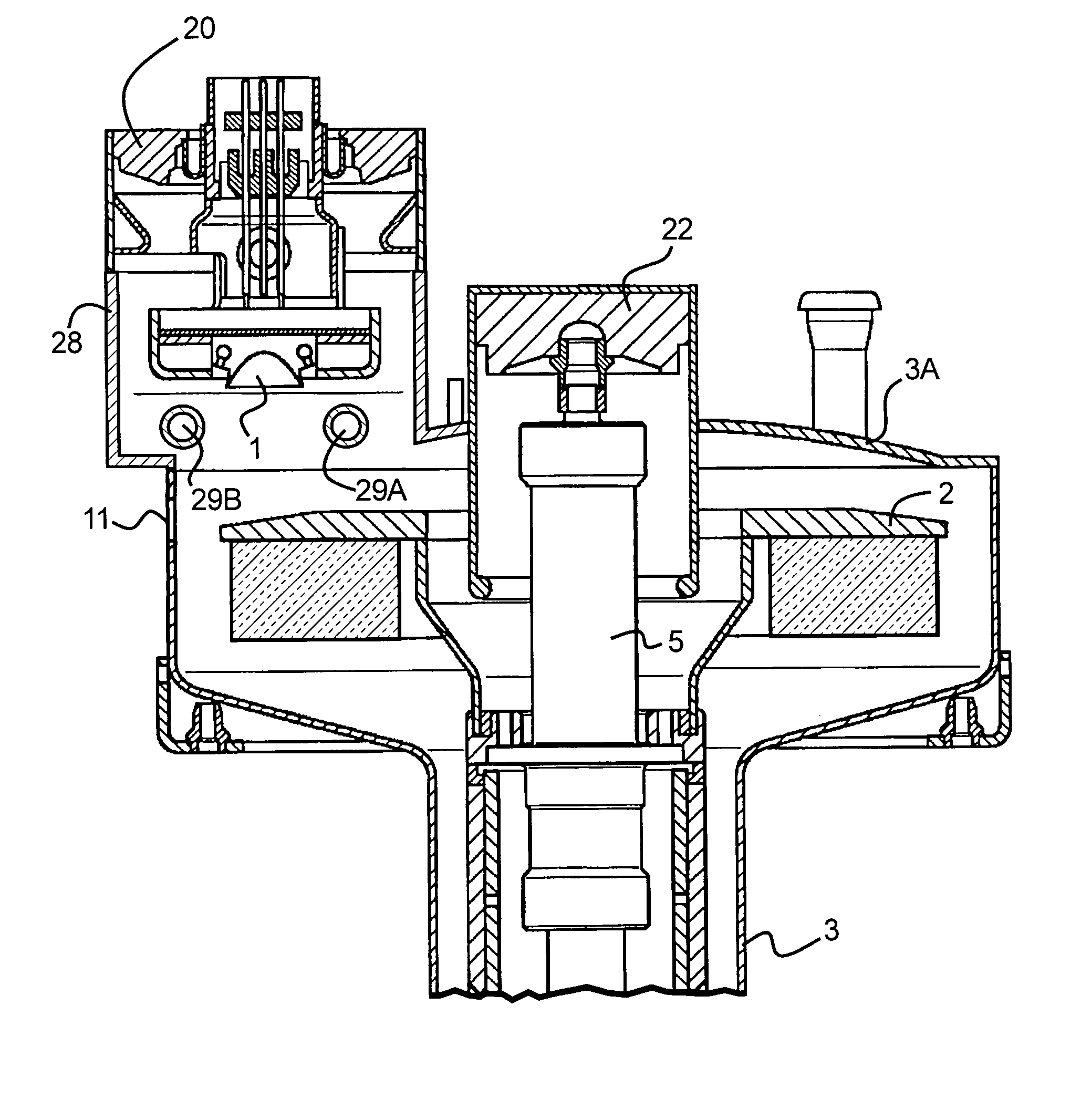
[0022] The X-ray tube according to FIG. 1 has a fixed cathode 1 and a rotating anode, generally referenced 2, that are arranged in a vacuum-tight evacuated housing 3 that is in turn disposed in a protective housing 4 filled with an electrically insulating, liquid cooling agent, for example insulating oil. The rotating anode 2 is rotatably mounted on a fixed shaft 5 in the vacuum housing 3 via two roller bearings 6 and 7 and a bearing sleeve 8.

[0023] The rotating anode 2, that is rotationally symmetric relative to the center axis M of the shaft 5, has an impact region that is provided with a layer 9 of tungsten-rhenium alloy, for example, that is struck by an electron beam 10 originating from the cathode 1 for the generation of X-rays. Only the center axis of the electron beam 10 is shown in FIG. 1, as a broken line. The interaction of the el...


PUM


Abstract

An X-ray source has an evacuated housing containing an interior space and a housing projection having a projection interior communicating with the interior space. A cathode is mounted in the projection interior and an anode is mounted in the interior space. Two tubes proceed substantially parallel to each other through the projection and are sealed relative to the projection interior, the two tubes being disposed on opposite sides of an electron beam that proceeds from the cathode to the anode during operation of the X-ray source. An electromagnetic electron beam deflector has a U-shape with two legs that are respectively disposed in the tubes. The electron beam deflector is controllable to generate a magnetic field that deflects the electron beam to set a position of the focus on the anode.

Description

BACKGROUND OF THE INVENTION [0001] 1. Field of the Invention [0002] The present invention is directed to a rotating anode X-ray tube, and in particular to a rotating anode X-ray tube of the type having a deflector that interacts with the electron beam proceeding from the cathode to the anode to influence the position of the focus on the anode. [0003] 2. Description of the Prior Art [0004] In the case of a rotating anode X-ray tube, it is known to provide a vacuum housing wherein the rotating anode is mounted in a larger volume of the housing, and the cathode is disposed in a generally cylindrical projection of the housing, having an interior that communicates with the larger volume in which the anode is disposed. The cylindrical projection is connected to the larger volume of the housing by a neck having a reduced diameter compared to the cylindrical projection in which the cathode is disposed. The electron beam emitted by the cathode proceeds through this neck and strikes the anode...

Claims


Application Information

Patent Timeline
Patent Type & Authority Applications(United States)
IPC IPC(8): H01J35/10H01J35/14H01J35/30
CPCH01J35/14H01J35/10H01J35/153
Inventor NEUMEIER, ERNSTKUTSCHERA, WOLFGANG
Owner SIEMENS AG
Why Eureka
Try Eureka