Film-covered electric device having pressure release opening

a technology of electric devices and films, applied in the direction of electrical apparatus casings/cabinets/drawers, cell components, hermetically sealed casings, etc., can solve the problems of battery explosion, large gas quantity, and pressure inside the battery, and achieve the effect of reducing the sealing reliability of an electric device elemen

Active Publication Date: 2005-07-21
NEC CORP
View PDF1 Cites 53 Cited by
  • Summary
  • Abstract
  • Description
  • Claims
  • Application Information

AI Technical Summary

Benefits of technology

[0014] An object of the invention is to provide a film-covered electric device in which a release pressure at the time of film expansion due to abnormal gas generation is easily set without reducing the sealing reliability of an electric device element.
[0016] According to the film-covered electric device of the invention constructed as described above, since the casing film have cove-like unfused portion communicating with the electric device element receiving portion, when the inside pressure goes up due to gas generation from the electric device element, the generated gas enters the unfused portions to expand the casing film at the unfused portions. The expansion of films at the unfused portions causes peeling of the casing film at the stress concentrating portion so as to proceed in advance of the other portions of the sealing area. The stress concentrating portion has the pressure release part formed thereon, and therefore, when the peeling at the stress concentrating portion proceeds to reach the pressure release part, the inside of the electric device element receiving part becomes connected to the outside thereof. This connection permits the generated gas to be ejected through the pressure release part, thereby preventing unexpected explosion of the film-covered electric device. Release pressure can be easily set by adjusting the position of the pressure release part on the stress concentrating portion. Additionally, the stress concentrating portion functioning as a safety valve can have larger progress in peeling film than that of conventional structures, thereby allowing the pressure to be released by lower value than a conventional one, and improving the precision of setting the release pressure with less influence of positional error of the pressure release part.
[0017] Preferably, the sealing area is formed protruding into the area where the unfused portions are provided. With this structure, the sealing area necessary to seal the electric device element can be maintained sufficiently even at the area where the unfused portions are provided, and further can suppress ingress of water contained in the atmosphere through the end of the casing film.
[0019] According to the invention, the sealing area has cove-like unfused portions, and the stress concentrating portion is provided touching the unfused portions, so that the peeling of casing film can proceed in advance at the stress concentrating portion. Resultantly, the release pressure can be set easily and securely.

Problems solved by technology

If a voltage over a rated range is applied to a battery during use of the battery, electrolytic solution is possible to be electrolyzed to generate gas, and the rise of pressure inside the battery results.
However, if failure of a control circuit for the battery occurs due to some causes, and a resultant abnormal voltage is applied or surrounding temperature abnormally rises, large quantities of gas may be possibly generated.
Extreme rise of the inside pressure is possible to cause the battery to be exploded if worst comes to worst.
However, the film-covered battery, which uses the casing films, is difficult to adopt a pressure relief valve because of its structure.
When the inside pressure excessively goes up in the film-covered battery, the casing films expand, and finally explodes to eject the gas from a broken position, which is possible to affect surrounding equipment according to the broken position, because it is difficult to determine the position to break.
However, the structures for releasing the gas in the conventional film-covered batteries described above have a risk of trouble, such as the leakage of electrolyte, due to the deterioration of the thermally fused portion.
Additionally, it has been difficult to adjust the thermo-fusing strength, that is, difficult to accurately set the release pressure at the time of occurrence of abnormality.
This structure has caused the sealing reliability to be reduced, and the width error of fused portion at the time of manufacturing has greatly affected the release pressure, resulting in difficulty accurately setting the release pressure.
The problem described above commonly arises not only in the batteries but also in film-covered electric devices in which an electric device element, having the possibility of generating gas, is sealed with casing films.

Method used


Image

  • Film-covered electric device having pressure release opening
  • Film-covered electric device having pressure release opening
  • Film-covered electric device having pressure release opening

Examples


Embodiment Construction

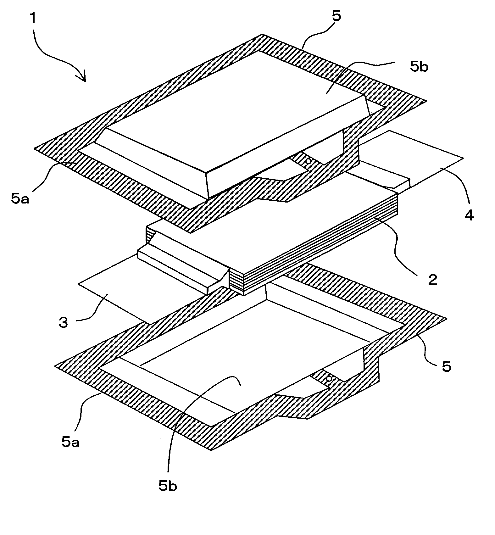
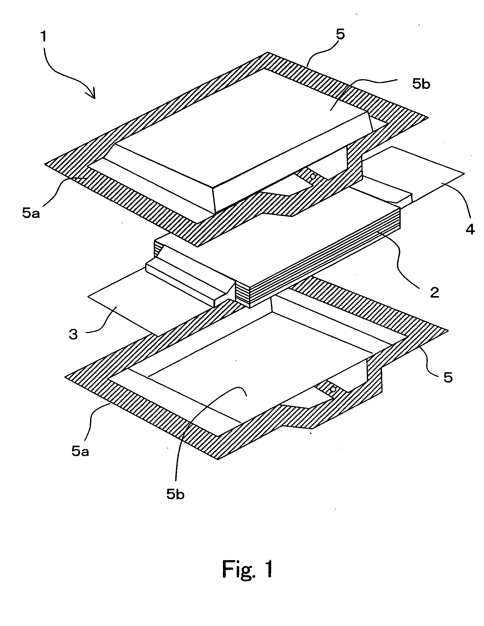
[0035] Referring to FIG. 1, film-covered battery 1 includes flat and substantially rectangular parallelepiped battery element 2 having a structure with a plurality of positive electrodes and negative electrodes alternately stacked, positive electrode lead 3 and negative electrode lead 4 connected with the positive electrodes and negative electrodes of battery element 2, respectively, and casing films 5 for sealing battery element 2 with positive electrode lead 3 and negative electrode lead 4 partially extending out, thus constructing film-covered battery 1 according to one embodiment of the present invention.

[0036] Battery element 2 has a stacked body wherein the plurality of positive electrodes and negative electrodes alternately stacked with separators intervened, the electrodes being composed of metallic foils both sides of which respective electrode materials are applied onto. The stacked body, including the positive electrodes, negative electrodes and the separators, is impreg...


PUM

PropertyMeasurementUnit
atmospheric pressureaaaaaaaaaa
widthaaaaaaaaaa
thicknessaaaaaaaaaa

Abstract

A film-covered electric device has an electric device element and casing films. The casing films include a sealing area formed by thermally fusing the facing surfaces of the casing films together around the periphery of the electric device element, an electric device element receiving part encapsulating the electric device element inside the sealing area, and unfused portions formed in the shape of cove communicating with the electric device element receiving part. The casing films further include a stress concentrating portion touching the unfused portions for concentrating thereon the peeling stress of the casing films generated at the sealing area by the expansion of the electric device element receiving part, and a pressure releasing part is formed in the stress concentrating portion.

Description

BACKGROUND OF THE INVENTION [0001] 1. Field of the Invention [0002] The present invention relates to a film-covered electric device in which casing films encapsulate therein an electric device element, such as a battery and a capacitor. [0003] 2. Description of the Related Art [0004] Recently,there has been a growing demand for lighter weight and thinner dimension of a battery as a power source for portable equipment or the like. As a casing for the battery, a laminated film structure has been increasingly used instead of a conventional metallic can, because the laminated film structure is possible to achieve lighter weight and thinner dimension and have flexibility in forming shapes, compared with the metallic can, which has some limitations in achieving lighter weight and thinner dimension with less flexibility. The laminated film includes a metallic thin film layer or metallic foil and thermo-fusing resin film layers. [0005] The laminated film structure used in the battery casing...

Claims


Application Information

Patent Timeline
Patent Type & Authority Applications(United States)
IPC IPC(8): H01G4/224H01G2/14H01G9/08H01M50/119H01M50/121H01M50/124H01M50/129H01M50/133H01M50/136
CPCH01G9/08H01M2/0275Y10T428/239H01M2/12Y02E60/13H01M2/08Y02E60/10H01M50/30H01M50/133H01M50/121H01M50/129H01M50/124H01M50/136H01M50/119H01M50/183H01M50/20
Inventor MIZUTA, MASATOMOYAGETA, HIROSHIOTOHATA, MAKIHIROOIKAWA, KIYOKAZUMANKYU, TOSHIHIKO
Owner NEC CORP
Why Eureka
Try Eureka