

Endoscope apparatus
a technology of endoscope and endoscope, which is applied in the field of endoscope equipment, can solve problems such as damage to the first balloon, and achieve the effect of preventing damage to the balloon
- Summary
- Abstract
- Description
- Claims
- Application Information
AI Technical Summary
Benefits of technology
Problems solved by technology
Method used
Image

Examples
first embodiment
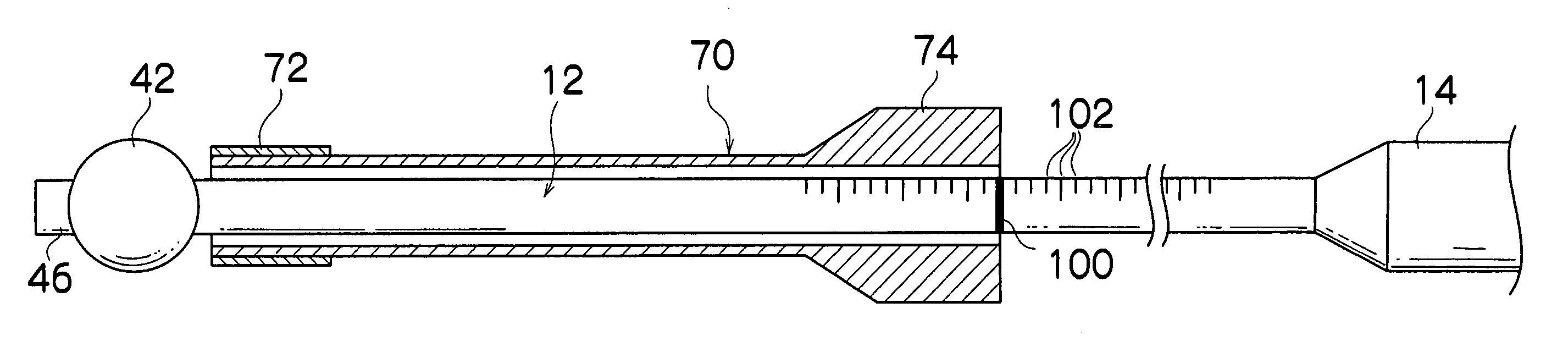
[0051]FIG. 4 is a schematic view showing a construction of the contact preventing device.
[0052] A contact prevention indicator 100 for contact prevention is formed on the outer peripheral surface of the insertion 12 shown in FIG. 4. The contact prevention indicator 100 is formed at the position where it appears from the base end side of the insertion assisting tool 70 when the tip end of the insertion assisting tool 70 is in the state in which the tip end of the insertion assisting tool 70 approaches the first balloon 42, but does not contact the first balloon 42 (hereinafter, called a limit state) as shown in FIG. 4. When scales 102 and the like are formed on the insertion section 12, it is preferable to form the contact prevention indicator 100 to be different in thickness, color, shape and the like from the scale 102 to be recognized as the contact prevention indicator 100 at a glance. For example, it is preferable to form the contact prevention indicator 100 to be thicker than t...
second embodiment
[0056]FIG. 5 is a schematic view showing a construction of the contact preventing device.
[0057] A string-shaped member 110 shown in FIG. 5 has its both ends respectively connected to the insertion assisting tool 70 and the hand operation section 14. As the string-shaped member 110, a chain, a string or the like, which is not extended in the axial direction is used, and the maximum length of the string-shaped member 110 is set at the distance between the insertion assisting tool 70 and the hand operation section 14 in the limit state. It is suitable to connect the both ends of the string-shaped member 110 to the insertion assisting tool 70 and the hand operation section 14 after covering the insertion section with the insertion assisting tool 70.
[0058] According to the second embodiment constructed as described above, when the insertion assisting tool 70 is pushed to the tip end side of the insertion section 12, the string-shaped member 110 strains when the insertion assisting tool ...
third embodiment
[0061]FIG. 7 is a schematic view showing a construction of the contact preventing device.
[0062] A recessed groove 120 is formed in an inner peripheral surface of the insertion assisting tool 70 shown in FIG. 7, and a ring-shaped reflector plate 122 is embedded in and fixed to the recessed groove 120. The reflector plate 122 is disposed to be detected by an optical sensor 124 when the insertion assisting tool 70 is in the limit state.
[0063] The optical sensor 124 is fixed to the insertion section 12. The optical sensor 124 irradiates light from the outer peripheral surface of the insertion section 12 and receives the reflected light, and thereby, detects the change in the reflected light amount. Accordingly, if the reflector plate 122 is disposed at the outer side of the optical sensor 124, the reflected light amount changes, and therefore, the optical sensor 124 can detect the reflector plate 122.
[0064] A cable 126 is connected to the optical sensor 124, and the cable 126 is conne...
PUM
 Abstract
Description
Claims
Application Information