Movable bed

Inactive Publication Date: 2005-07-28
SANYO ELECTRIC CO LTD
View PDF54 Cites 53 Cited by
  • Summary
  • Abstract
  • Description
  • Claims
  • Application Information

AI Technical Summary

Benefits of technology

[0006] In view of the above problem, the present invention aims to provide an adjustable bed capable of facilitating post

Problems solved by technology

Apart from requiring considerable strength on the part of the caregiver, the care recipient may be caused both physical discomfort due to the caregiver's lack of experience in performing this difficult task,

Method used


Image

  • Movable bed
  • Movable bed
  • Movable bed

Examples


embodiment 1

1. Embodiment 1

1.1 Structure of Turning Bed

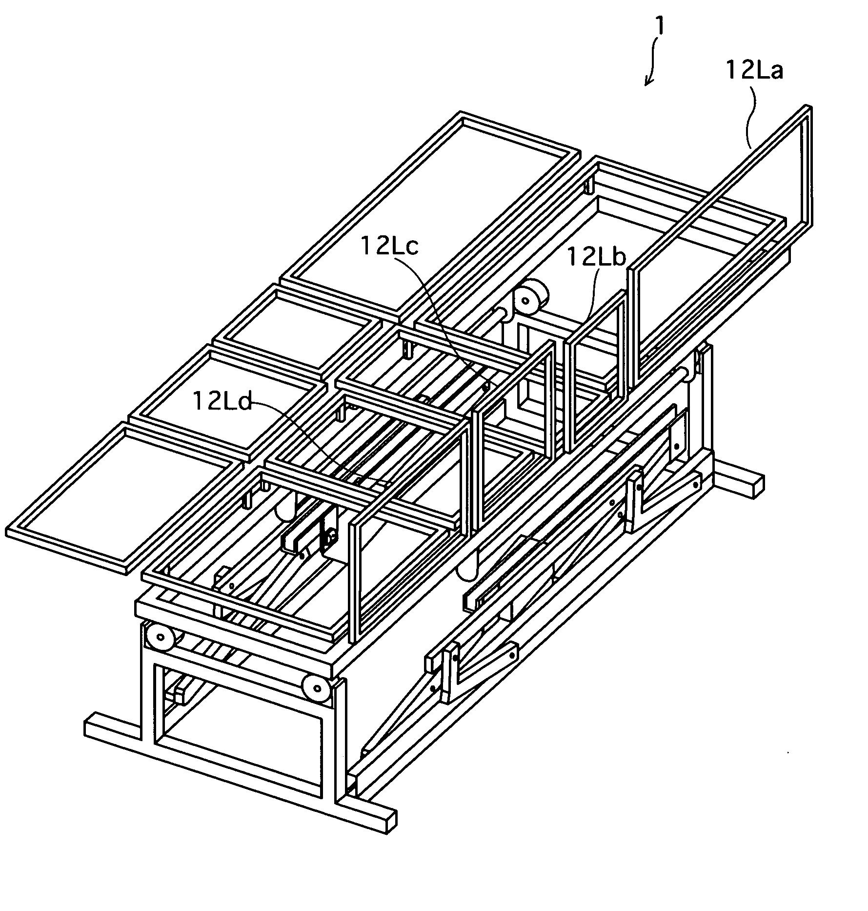
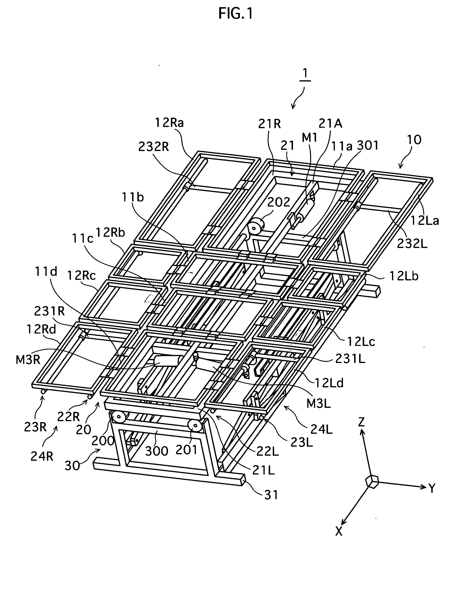
[0046]FIG. 1 is a perspective view showing a structure of a turning bed 1 relating to an embodiment 1 of the present invention.

[0047] Turning bed 1 is constituted such that a bed frame 10 is disposed on an adjustable stage 20 sitting on a fixed stage 30.

[0048] Bed frame 10 includes coupled platforms 11a to 11d, which are formed by dividing a surface section (i.e. upper surface of the bed) into four articular sections corresponding to the back, hip, upper leg, and lower leg regions of the care recipient's body when lying on the bed, and coupling these sections together so as to be fully adjustable. Of these four coupled platforms 11a-11d, lower-back board 11b is fixed directly to adjustable stage 20 by being welded, for example, thus preventing bed frame 10 from separating from adjustable stage 20. Side members 12Ra-12Rd and 12La-12Ld for supporting the care recipient's body from the side are coupled to platforms 11a-11d on the right and...

embodiment 2

2. Embodiment 2

[0114]FIG. 25A is a perspective view showing a structure of a turning bed in an embodiment 2.

[0115] While the bed structure in embodiment 1 is driven using parallelogram mechanisms, in embodiment 2, direct-acting actuators are disposed vertically, and side members on the left or right are elevated vertically using elevation mechanisms, thus enabling platforms positioned above an adjustable stage to be titled.

[0116] With the turning bed of embodiment 2, a pair of columnar direct-acting actuators is disposed within a rectangular fixed stage, and a bed frame supported by an adjustable stage is positioned on top of the actuators. The platforms, as in embodiment 1, are constructed as coupled platforms that are coupled together by a plurality of joints corresponding to the care recipient's upper body, hip, upper leg, and lower leg regions. Of these, the section corresponding to the upper-leg board is secured to the adjustable frame, which has a frame construction equivale...

embodiment 3

3. Embodiment 3

[0119]FIGS. 26A to 26F show a structure of a turning bed in an embodiment 3.

[0120] The turning bed in embodiment 3, which can be used with general-purpose beds, is constituted by laying an air mattress formed from a plurality of airbags on a general-purpose bed. A characteristic of this turning bed is the use of an air pump (not depicted) to supply / discharge air independently for each airbag via an air hose. The air hose has a valve that is controlled to open / close by a control unit (not depicted), thus controlling the inflation / deflation of respective airbags. The airbags are, as one example, partitioned into upper body (double layer), lower back (double layer), upper leg, lower leg, and both sides of the bed so as to correspond to the joints of the care recipient's body.

[0121] A turning bed having the above structure is normally used with a mattress or the like placed over the air mattress. When turning the care recipient from a supine to a lateral position, the u...


PUM


Abstract

An adjustable bed includes a platform having a flexible surface, a flex mechanism adapted to flex the platform to form a flexion position that includes at least one of a sitting-up position and a knee break, and a tilt mechanism adapted to tilt the platform surface laterally, the flex and tilt mechanisms both being operable with the other mechanism in an operational state. Furthermore, the adjustable bed includes a side member disposed on a side of the platform, and a side-member lift mechanism adapted to raise the side member relative to the platform surface, the tilt mechanism tilting the platform surface toward the side member raised by the side-member lift mechanism.

Description

TECHNICAL FIELD [0001] The present invention relates to adjustable beds for use in nursing care and the like, and particularly to improving the mechanism for turning users of the bed, such as care recipients, between supine and lateral positions. BACKGROUND ART [0002] Generally, with adjustable beds used as turning beds and the like to assist the postural change of care recipients in order to prevent the occurrence of decubitus ulcers, more commonly known as bedsores, the person is turned by tilting at least part of the mattress on which the person is lying at an angle (see Japanese Published Patent Publication No. 6-14824). The majority of these types of beds employ a mechanism that tilts the mattress toward one side or the other from a horizontal position. [0003] Using this mechanism employed in turning beds, the posture of the care recipient is changed from a position lying flat on a horizontal mattress (i.e. supine) to a lateral position in which the person is lying on either th...

Claims


Application Information

Patent Timeline
IPC IPC(8): A47C20/08A61G7/00A61G7/008A61G7/015A61G7/057
CPCA61G7/001A61G7/008Y10S5/942A61G7/05769A61G2203/42A61G7/015
Inventor TAGUCHI, KENJIABE, HIROSHIMORIKAWA, MASASHIKAWAKAMI, HIDEOOGAWA, ATSUSHI
Owner SANYO ELECTRIC CO LTD
Why Eureka
Try Eureka