Anti-rotation fuel injector clip

Inactive Publication Date: 2005-07-28
DELPHI TECH INC
View PDF6 Cites 24 Cited by
  • Summary
  • Abstract
  • Description
  • Claims
  • Application Information

AI Technical Summary

Benefits of technology

[0010] Briefly described, an anti-rotation clip for joining a fuel injector body to a fuel rail socket includes a flat, C-shaped base that is formed to slide into, and be retained in, an annular groove in the injector body. A pair of curved tangs extend from the base to straddle a longitudinal rib on the injector body to prevent rotation between the clip and the injector. Opposed sidewalls extend from the base in the opposite direction. A window is formed in each sidewall for receiving a radial flange of a fuel rail socket to correctly position the fuel injec

Problems solved by technology

The alignment protrusion of this device can provide resistance to relatively low rotational forces on the fuel injector; however, progressively higher torque can deform the clip base and twist the protrusion out of engagement with the socket flange.
At least one automotive manufacturer has now increased the minimum torque resistance of such a joint from 1.5 Nm to 3.0 Nm, and, because of the bending moment placed on the base of

Method used


Image

  • Anti-rotation fuel injector clip
  • Anti-rotation fuel injector clip
  • Anti-rotation fuel injector clip

Examples


Example

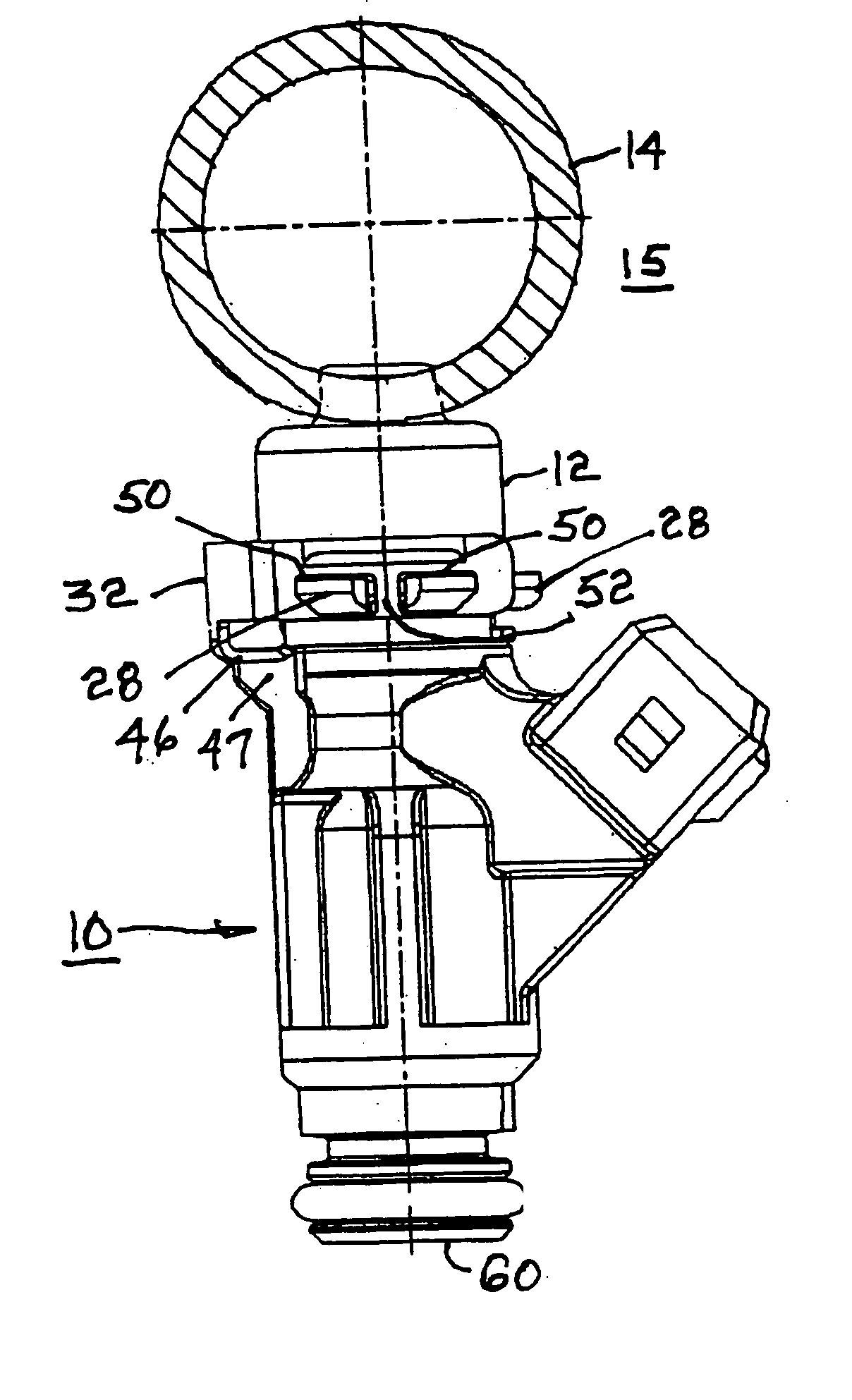
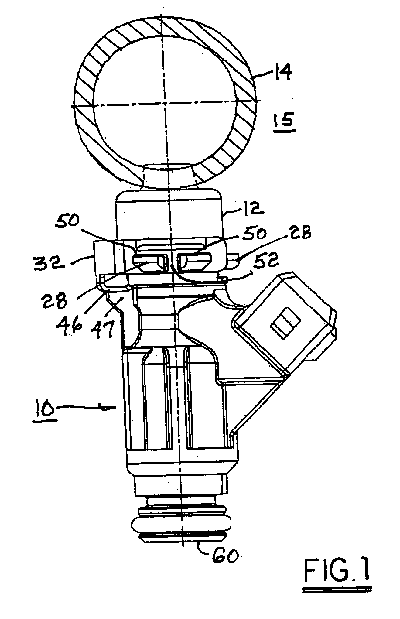
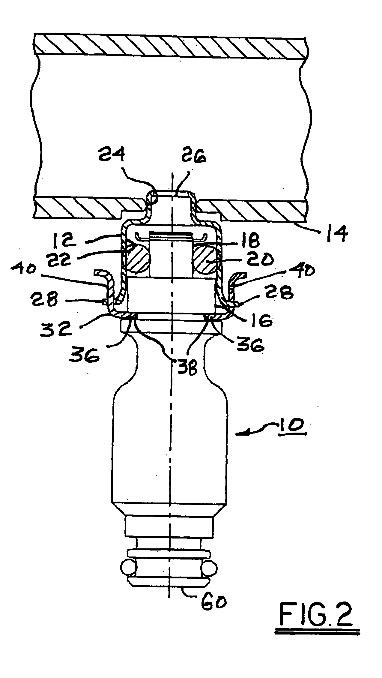
[0020] Referring to FIGS. 1, 2, 7, and 8, a conventional fuel injector 10 is coupled into a socket 12 of a fuel rail 14 of an internal combustion engine 15. A first necked portion 16 and second necked portion 18 of injector 10 supporting an O-ring 20 extend into socket 12 forming a fuel-tight seal against the inner surface 22 thereof. Socket 12 itself is brazed or welded into a port 24 in the wall of fuel rail 14. A central opening 26 in socket 12 allows fuel to flow as required from fuel rail 14 into injector 10. Socket 12 has an outer flange 28 that is preferably slightly flared or rolled outwards, as shown in FIG. 8, to help in guiding injector 10 into mating relationship. Flange 28 is provided with one or more notches 30 extending through the outer part of the flange for engaging anti-rotation means as described below.

[0021] Referring now additionally to FIGS. 3 through 6, an anti-rotation clip 32 in accordance with the invention is provided for securing injector 10 into socket...


PUM


Abstract

An anti-rotation clip for joining a fuel injector body to a fuel rail socket. A C-shaped base is formed to slide into an annular groove in the injector body. A pair of tangs extend from the base to straddle a rib on the injector body to prevent rotation between the clip and the injector. Opposed sidewalls extending from the base include windows for receiving a radial flange of the fuel rail socket to correctly position the fuel injector axially within the socket. Each window is divided by a locking bar for reception in a notch in the socket flange to prevent rotation between the clip and the socket. The radial positions of the injector rib and flange notch are selected such that the injector will be properly oriented with respect to the engine after installation therein.

Description

TECHNICAL FIELD [0001] The present invention relates to internal combustion engines; more particularly, to devices for securing fuel injectors into fuel distribution rails; and most particularly, to a clip for providing such securing and also preventing subsequent rotation of the fuel injector with respect to the fuel distribution rail and engine. BACKGROUND OF THE INVENTION [0002] Means for attaching and securing of fuel injectors to fuel distribution rails of internal combustion engines is well known. Typically, a formed metal clip is employed to urge the body of a fuel injector into a cup-shaped socket element previously pressed into a port in the fuel rail, the injector body having means such as an O-ring for sealing against the inner surface of the socket. See, for example, U.S. Pat. Nos. 6,276,339 and 6,637,411. [0003] In 4-valve engines, the relationship between the fuel injector spray pattern and the intake valves in the valve port can be critical and requires a specific ori...

Claims


Application Information

Patent Timeline
IPC IPC(8): F02M61/14F02M63/02
CPCF02M63/0225F02M61/14
Inventor BRAUN, CHARLES W.DELANEY, JOHN H.ROGERS, DAVID W.
Owner DELPHI TECH INC
Why Eureka
Try Eureka