Papermaking apparatus

a papermaking apparatus and papermaking technology, applied in the field of papermaking apparatuses, can solve the problems that the papermaking apparatus generally has little use for the tube-type board, and achieve the effects of improving paper quality, enhancing the natural harmonic pitch and improving the versatility of the papermaking apparatus

Inactive Publication Date: 2005-07-28
GL & V MANAGEMENT HUNGARY KFT
View PDF3 Cites 2 Cited by
  • Summary
  • Abstract
  • Description
  • Claims
  • Application Information

AI Technical Summary

Benefits of technology

[0005] The present invention seeks to improve the versatility of a papermaking apparatus by introducing into the forming area an assembly of forming elements which together define a discontinuous supporting surface for the papermaking suspension. More particularly, the present invention relates to an assembly of forming elements which takes account of and enhances the natural harmonic pitch of the papermaking apparatus to accurately control in the forming area the drainage of and micro-turbulence in the papermaking suspension thereby satisfying a demand from customers for improved paper quality (eg improved fibre and fines dispersal throughout the sheet).
[0017] It will be apparent that the assembly of forming elements largely making up the forming area of the papermaking apparatus of the invention may be advantageously extended to any desired length to achieve the requisite formation characteristics simply by adding additional secondary support blades and additional drainage deckles (ie by increasing n). Moreover, in sharp contrast to conventional rigid forming boards, the forming elements of the papermaking apparatus of the invention may be assembled into the papermaking apparatus quite straightforwardly to the desired length. To exemplify its improved versatility, the papermaking apparatus may be used with a broader range of paper (or board) grades (eg varying in weight) than has hitherto been possible irrespective of the carrier speed.
[0023] Preferably the groove is adapted to transmit pulses of fluid (eg water) onto its upper surface. Preferably to an end wall of at least one (preferably more than one eg each) of the first drainage deckle and n consecutive additional drainage deckles extends a transverse slot (eg a transverse substantially circular slot) outwardly from a transverse end wall of the groove. Particularly preferably to a first and second end wall of at least one (preferably more than one eg all) of the first drainage deckle and n consecutive additional drainage deckles extends respectively a first and a second transverse slot (eg a transverse substantially circular slot) outwardly from a first and second transverse end wall of the groove respectively. The or each transverse slot is in fluid communication with the groove and therefore with the upper surface so that pulses of fluid (eg water) may be transmitted therethrough onto the upper surface. The depth of the groove, the nature of the means for generating micro-turbulence and the manner in which the means for generating micro-turbulence is applied may be judiciously chosen to refine the micro-turbulence generated intrinsically in the papermaking suspension (eg by dampening or amplifying the micro-turbulence imparted by the natural harmonic pitch of the forming elements) which in turn assists fibre formation and dispersal of fines throughout the sheet (ie improves sheet quality).
[0030] By substituting the forming elements of a conventional papermaking apparatus with the assembly as hereinbefore defined, the natural harmonic pitch of the conventional papermaking apparatus is advantageously enhanced in a controlled manner.

Problems solved by technology

It can be a disadvantage of conventional papermaking apparatus that the design is specified in accordance with certain grades of paper (or board) and certain types or quality of pulp.
Moreover the TURBOFORM™ board is generally of little use in a slow speed papermaking apparatus.

Method used


Image

  • Papermaking apparatus
  • Papermaking apparatus
  • Papermaking apparatus

Examples


Embodiment Construction

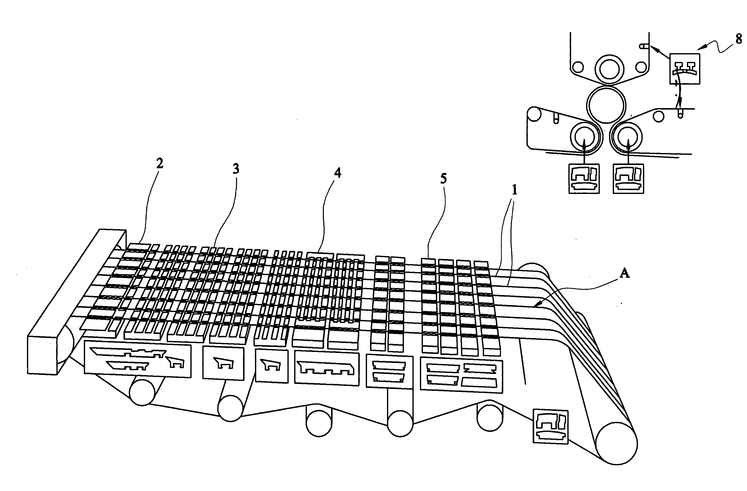
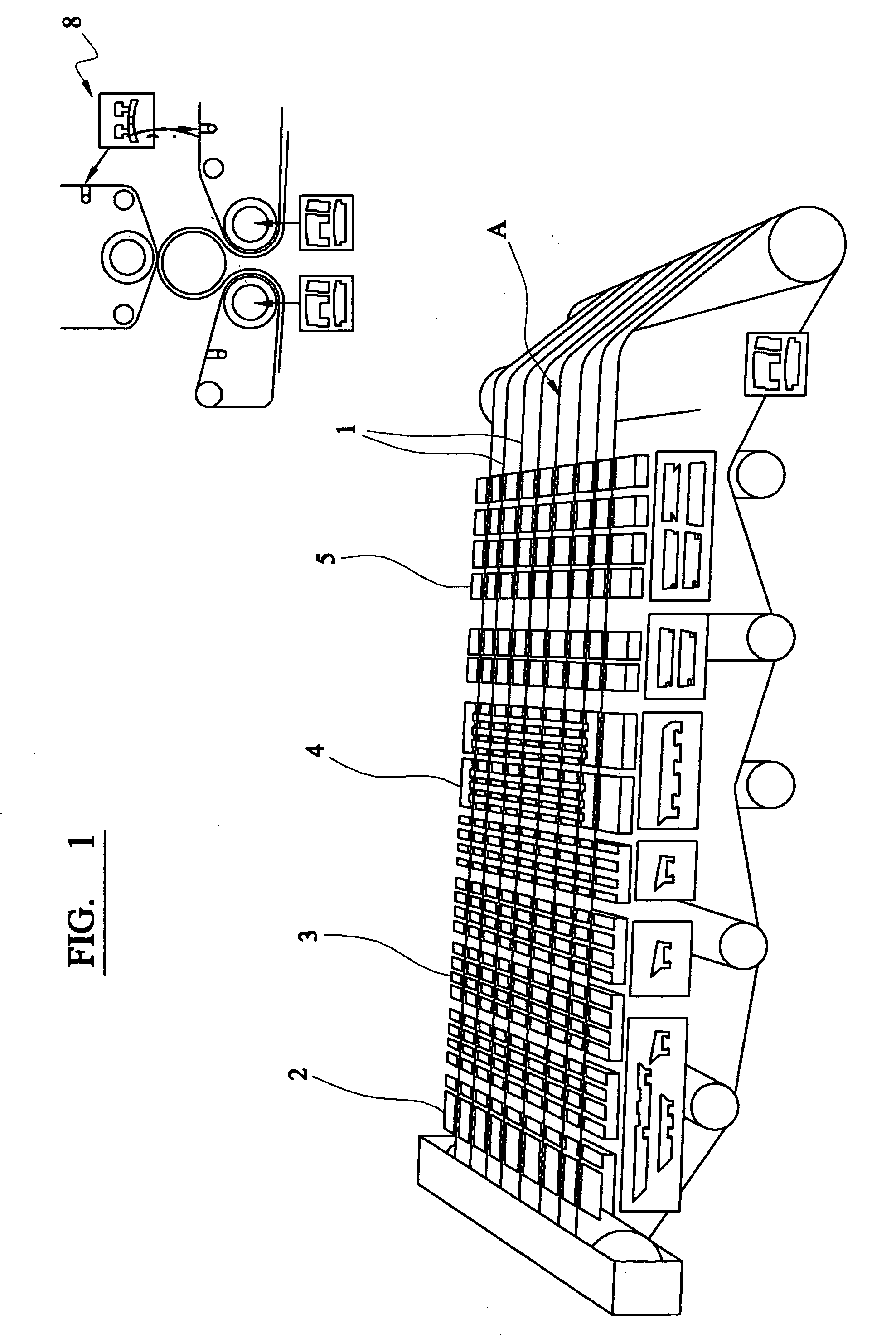
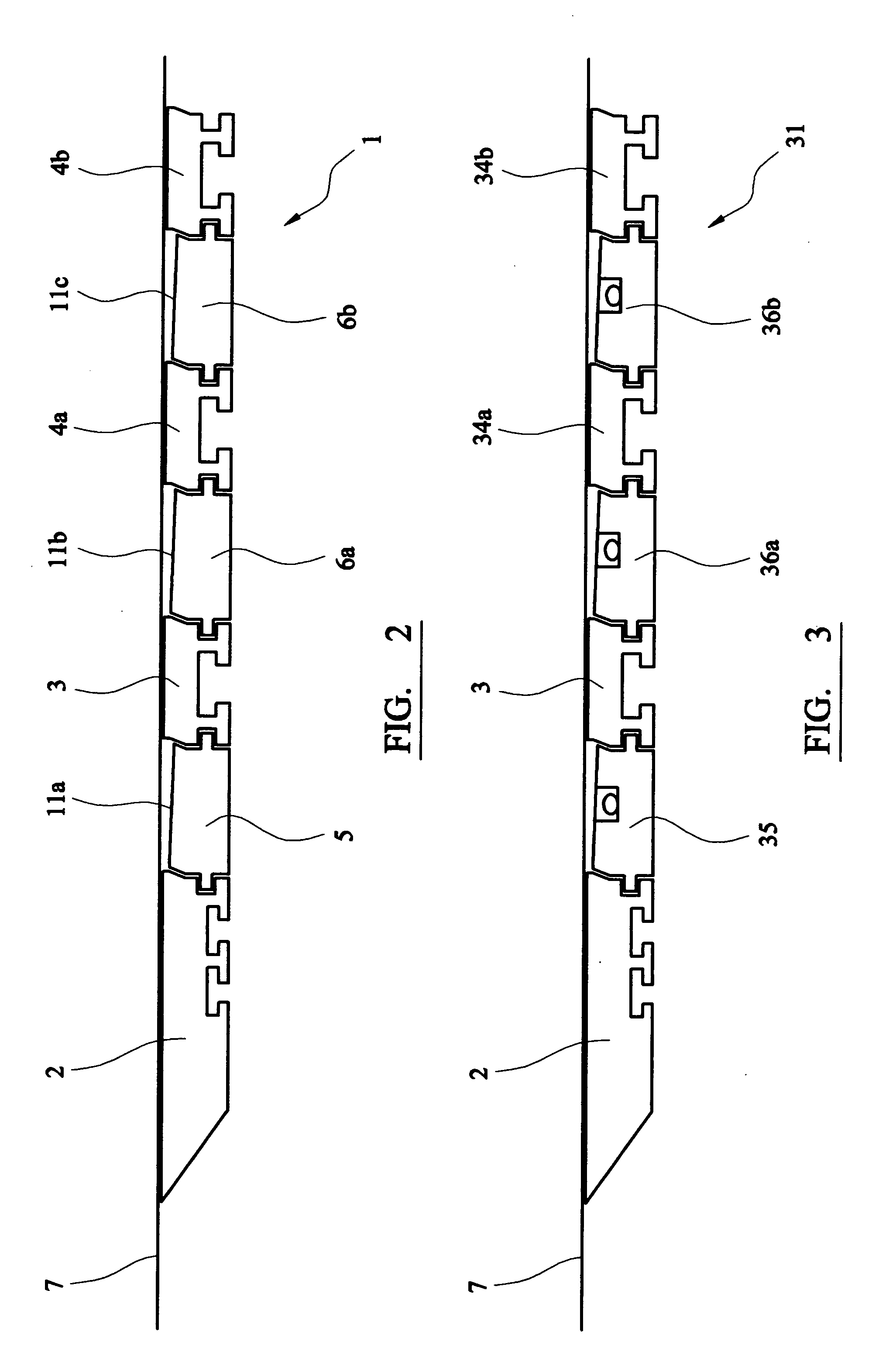
[0052]FIG. 2 illustrates schematically an isolated side view of the assembly of forming elements 1 of a first embodiment of a papermaking apparatus of the invention. The assembly of forming elements 1 includes a primary blade 2 positioned immediately after the one or more supply means (not shown), a first secondary support blade 3, first and second consecutive additional secondary support blades 4a and 4b, a first drainage deckle 5 and first and second additional drainage deckles 6a, 6b. The assembly of forming elements 1 defines a discontinuous upper surface for supporting the papermaking suspension carried by a papermaking wire 7.

[0053] The primary blade 2 is illustrated alone in FIG. 4. A trailing face 42a of the primary blade 2 tapers downwardly and forwardly. A leading face 41a of the primary blade 2 is perpendicular to the upper and lower surfaces and is provided with a shoulder 42 at its upper edge. The lower surface incorporates T-shaped slots 49a, 49b which engage T-shaped...


PUM


Abstract

The present invention relates to an assembly of forming elements which together define in a papermaking apparatus a discontinuous supporting surface for a papermaking suspension to permit drainage and micro-turbulence to be accurately controlled, and to the papermaking apparatus per se.

Description

TECHNICAL FIELD [0001] The present invention relates to an assembly of forming elements which together define in a papermaking apparatus a discontinuous supporting surface for a papermaking suspension to permit drainage and micro-turbulence to be accurately controlled, and to the papermaking apparatus per se. BACKGROUND OF THE INVENTION [0002] In the papermaking industry, various forming elements are deployed to promote the drainage of water from paper stock in its transformation from a papermaking suspension (or slurry) of fibres, water and chemicals (eg fillers) into a self-supporting web of cellulose fibres commonly referred to as a sheet (ie a sheet of paper or board). De-watering takes place in the forming area at the “wet end” of a papermaking apparatus, a typical one of which is illustrated schematically by way of example in FIG. 1. Thus in FIG. 1, parallel papermaking wires 1 (or mesh or a belt) move in direction A and are supported from beneath by discrete forming elements ...

Claims


Application Information

Patent Timeline
Patent Type & Authority Applications(United States)
IPC IPC(8): D21F1/48
CPCD21F1/483
Inventor AMOS, JOHNSALMON, ANTONY
Owner GL & V MANAGEMENT HUNGARY KFT
Why Eureka
Try Eureka