
Electroosmotic flow systems

a flow system and electrochemical technology, applied in the field of electrochemical systems, can solve problems such as unstable system operation, and achieve the effect of substantial charge ratio and fine pore siz

Inactive Publication Date: 2005-07-28
EKSIGENT TECH
View PDF8 Cites 2 Cited by
  • Summary
  • Abstract
  • Description
  • Claims
  • Application Information

AI Technical Summary

Benefits of technology

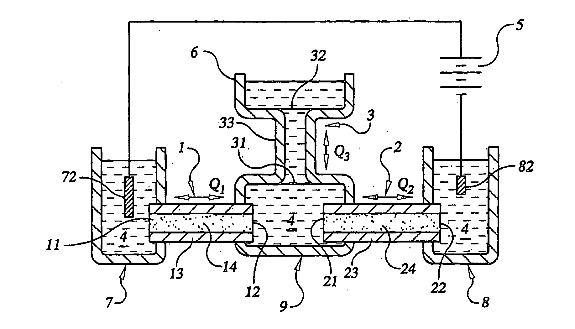
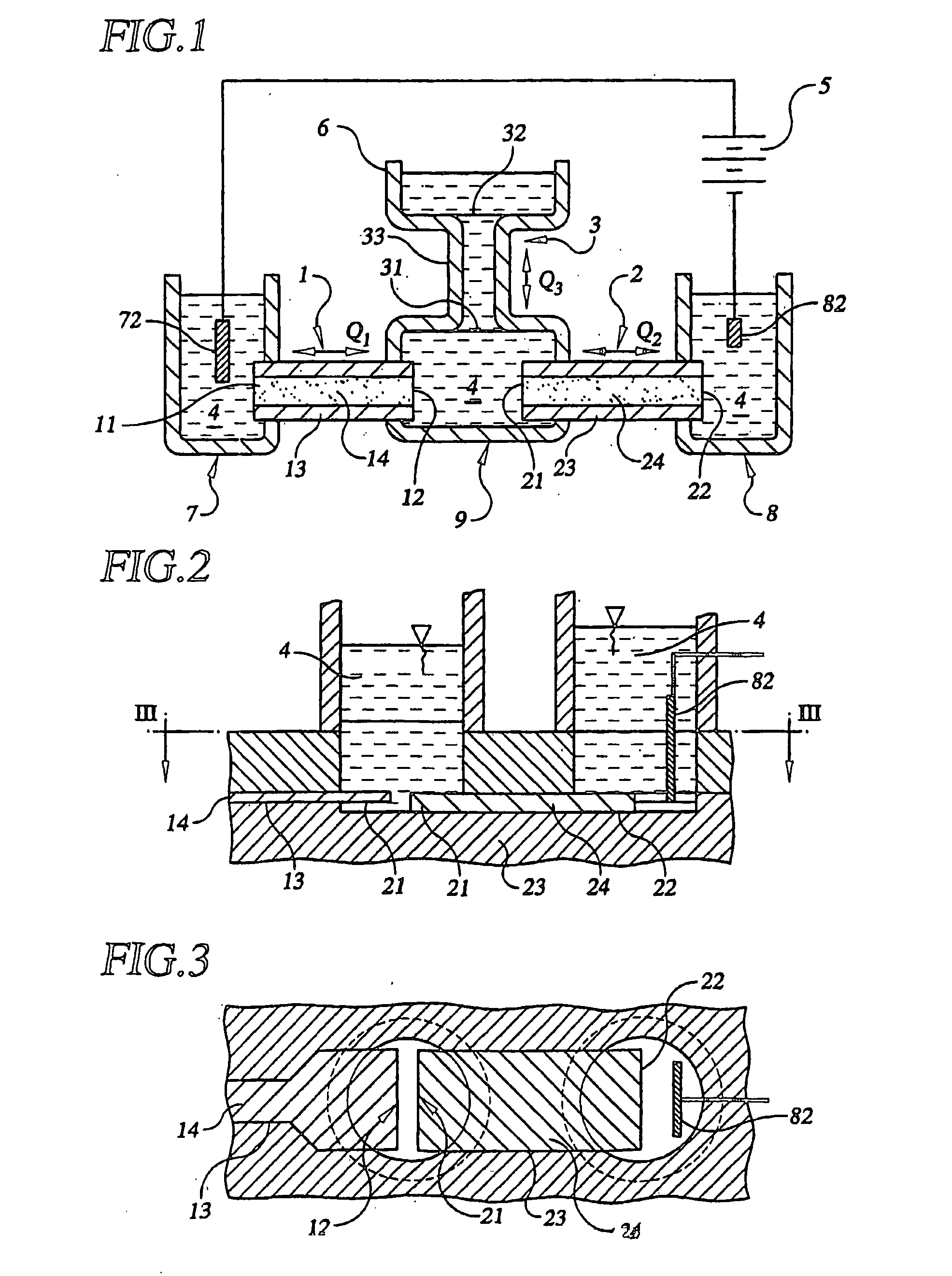
[0005] There is a need for EOF systems containing EOF elements which have substantial charge ratios, for example because they are very small and / or use materials having very fine pore sizes. Such systems are often unstable in operation. We have discovered, in accordance with the present invention, that in electroosmotic flow systems containing two or more EOF elements which are coupled to each other, any tendency towards unstable flow can be controlled by reducing the magnitude of the difference between the flux ratios of the EOF elements. The invention is particularly useful when the magnitude of the charge ratio of at least one of the EOF elements is substantial. One or both of the EOF elements can be a bridge between different parts of the EOF system, for example between an electrode-containing reservoir and the rest of the EOF system.

Problems solved by technology

Such systems are often unstable in operation.

Method used


Image

  • Electroosmotic flow systems
  • Electroosmotic flow systems
  • Electroosmotic flow systems

Examples


Embodiment Construction

[0102] In the Summary of the Invention above and in the Detailed Description of the Invention, the Examples, and the claims below, reference is made to particular features of the invention. It is to be understood that the disclosure of the invention in this specification includes all appropriate combinations of such particular features. For example, where a particular feature is disclosed in the context of a particular aspect or embodiment of the invention, or a particular Figure, or a particular claim, that feature can also be used, to the extent appropriate, in combination with and / or in the context of other particular aspects and embodiments of the invention, and in the invention generally.

[0103] The term “comprises”, and grammatical equivalents thereof, are used herein to mean that other components, ingredients, steps etc. are optionally present in addition to the component(s), ingredient(s), step(s) specifically listed after the term “comprises”. The term “at least” followed b...


PUM

PropertyMeasurementUnit
aspect ratioaaaaaaaaaa
pressureaaaaaaaaaa

Abstract

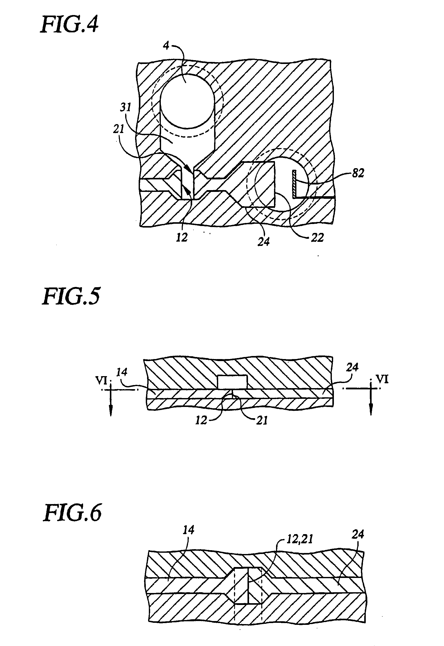
Electroosmotic flow systems containing two or more electroosmotic flow elements which meet at a junction, at least one of the electroosmotic flow elements having a substantial charge ratio. The electroosmotic flow elements have matching flux ratios. The electroosmotic flow elements may contain porous materials whose terminal portions are shaped to increase the surface area exposed to the fluid at the junction. Examples of such terminals are illustrated in the figure.

Description

RELATED APPLICATION DATA [0001] This application is a continuation-in-part of our application Ser. No. 10 / 137,215, filed May 1, 2002 (Docket No.14129), the entire disclosure of which is incorporated herein by reference.FIELD OF THE INVENTION [0002] This invention relates to electrochemical systems. BACKGROUND OF THE INVENTION [0003] In electroosmotic flow systems (hereinafter referred to as EOF systems), an electric field is applied to a liquid containing ions and causes the liquid to flow. In many electrochemical systems, including EOF systems, bridges are used to physically separate, but ionically connect, different parts of the system, e.g. to isolate electrodes and electrode by-products from a working liquid. Such bridges are disclosed in, for example, U.S. Pat. No. 3,923,426 (Theeuwes); Electrochemical detection for capillary electrophoresis (Doctoral dissertation, B. S. Seoul, U. Kansas, 1996, pp.136-141; Electrophoresis, 20, 525-528 (1999) Desiderio et al.; Micro Total Analys...

Claims


Application Information

Patent Timeline
Patent Type & Authority Applications(United States)
IPC IPC(8): G01N27/447G01N27/453
CPCG01N27/44752
Inventor PAUL, PHILLIP HNEYER, DAVID W.
Owner EKSIGENT TECH
Learn More