Hoisting apparatus for use at a manhole

a manhole and hoisting technology, applied in the field of hoisting apparatus, can solve the problems of manhole-ladder assembly not being able to quickly, easily and safely evacuate an injured person from the manhole, people having to go into such confined spaces, etc., to achieve safe support and evacuation, facilitate transportation, and facilitate the effect of mounting

Inactive Publication Date: 2005-07-28
9105 0732 QUEBEC
View PDF11 Cites 19 Cited by
  • Summary
  • Abstract
  • Description
  • Claims
  • Application Information

AI Technical Summary

Benefits of technology

[0010] As can be appreciated, a hoisting apparatus according to the invention comprises very few elements, which makes it easy and quick to mount and fairly lightweight in order to facilitate transportation thereof, while being structurally sound, in order to safely support and evacuate a person from the manhole.
[0011] Also, such minimal amount of elements provide for an easy maintenance and / or part replacement thereof.

Problems solved by technology

Often, people have to go into such confined spaces, with or without working material.
People working in manholes occasionally get seriously injured and, as a result thereof, require to be evacuated as quickly and as safely as possible from the manhole in order to be attended by a professional, such as a doctor and the like.
The above-mentioned type of manhole-ladder assembly does not enable to quickly, easily, and safely evacuate an injured person from the manhole.
These tripod hoists are however cumbersome and once installed over the manhole, they interfere with persons or equipment being passed over the manhole.
These apparatuses are however also cumbersome and, as for the tripod hoists, they extend right over the manhole once installed, thereby interfering with persons or equipment being passed over the manhole.
They are thus not very practical for an easy and rapid use.
One drawback with this hoist apparatus is that it is fragile and not suitable for hoisting very heavy persons or objects.
It has been shown that the joint connecting the jib portion to the post is not sufficient to resist to the flexion caused by the load hanging at the extremity of the jib portion.

Method used


Image

  • Hoisting apparatus for use at a manhole
  • Hoisting apparatus for use at a manhole
  • Hoisting apparatus for use at a manhole

Examples


Embodiment Construction

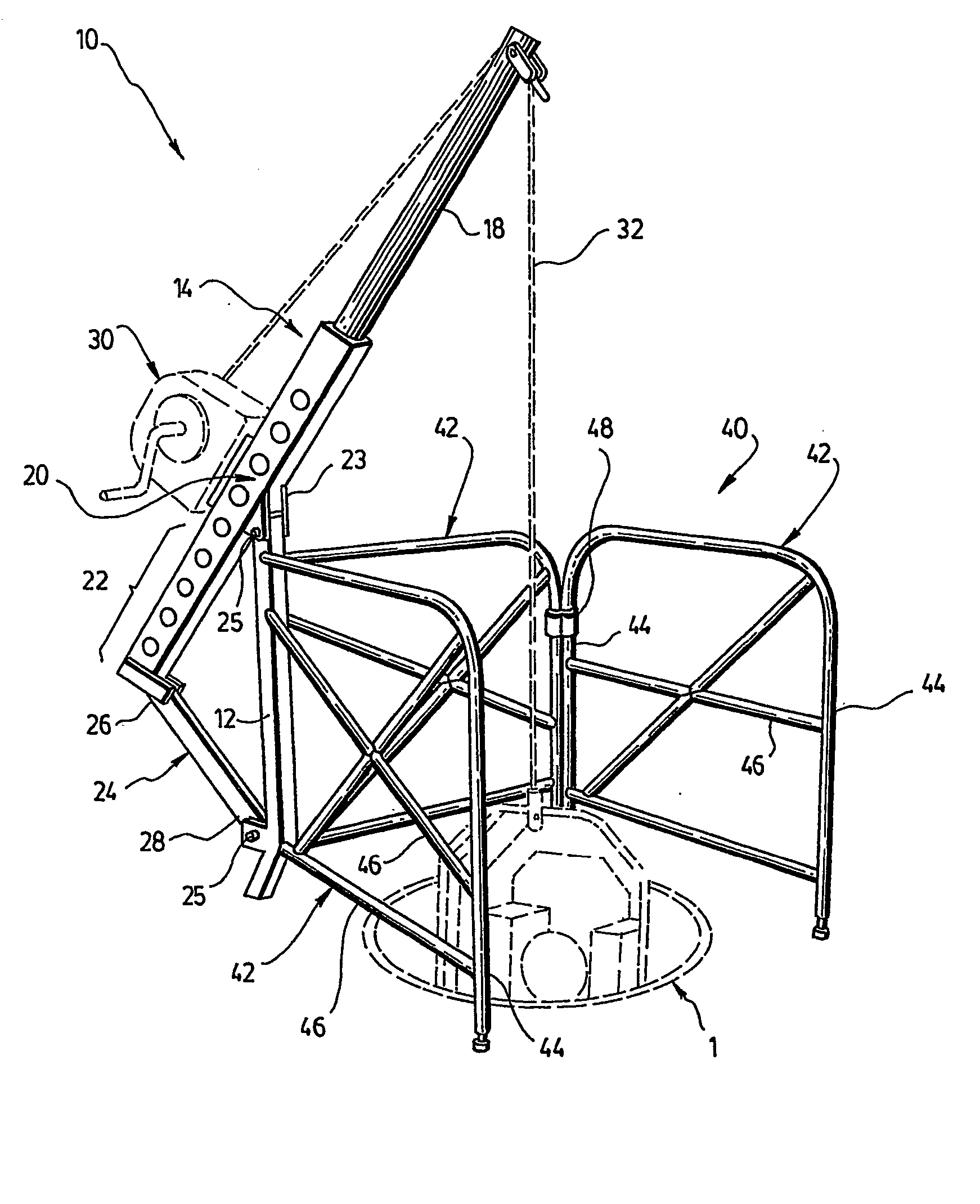
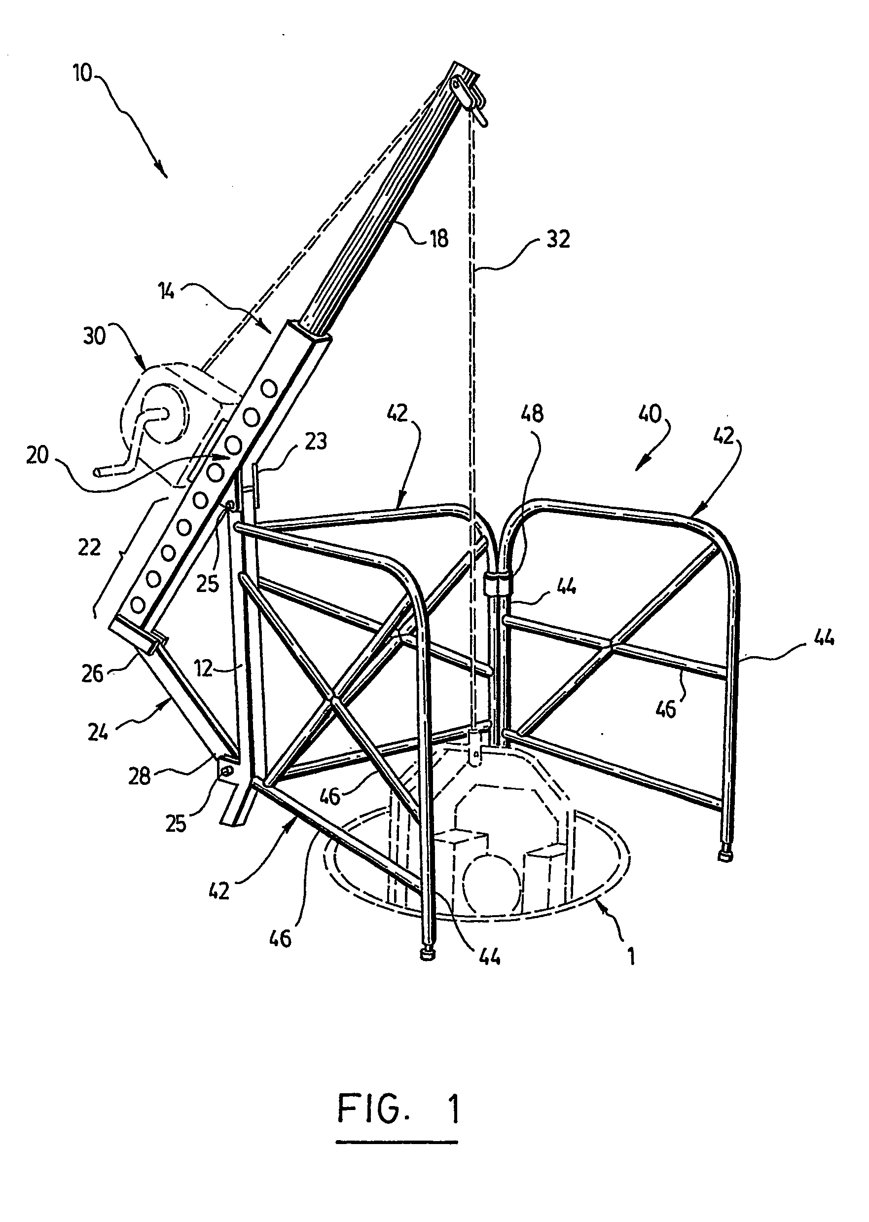
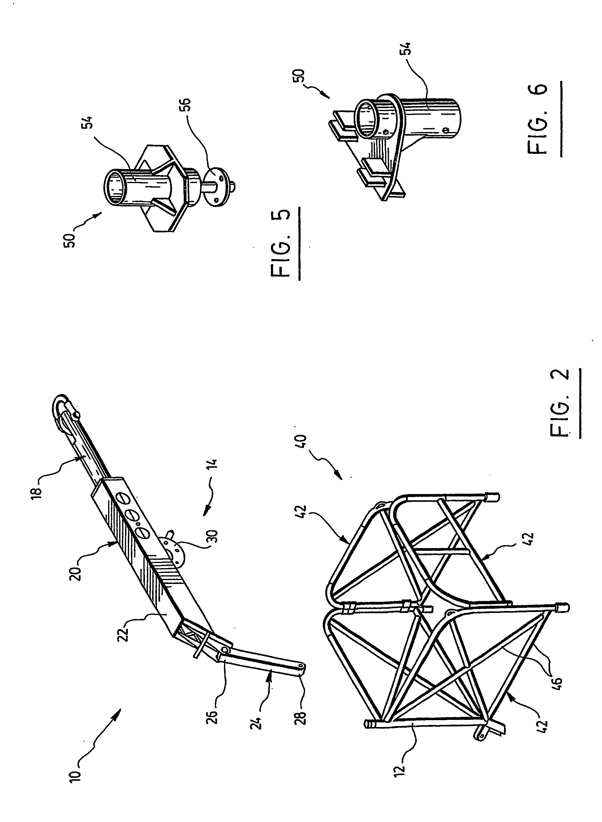
[0025] In the following description, similar features in the drawings have been given similar reference numerals and in order to lighten the figures, some elements are not referred to in some figures if they were already identified in a precedent figure.

[0026] Moreover, although the present invention was primarily designed for rescue purposes of individuals injured inside manholes so as to enable to evacuate them, it may be used for other applications and with other objects, such as a mining raise for example or for transportation of material, as apparent to a person skilled in the art. For this reason, the expressions “manhole”, “person” and “rescue” should not be taken as to limit the scope of the present invention and include all other kinds of objects and purposes with which the present invention could be used and may be useful. For example, the expression “manhole” refers to any horizontally extending hole giving access to an underground confined space or structure such as a s...


PUM


Abstract

A hoisting apparatus (10) for use at a manhole (1), comprising a supporting mast and a jib crane (14) connected at an angle to an upper end portion (16) of the supporting mast (12). The jib crane (14) has a front member (18) pointing upwardly and extending on one side of the supporting mast (12) and a rear member (20) having a rear end section (22) extending on another side of the supporting mast (12). A linking rod (24) is connecting the rear member of the jib crane (14) to the supporting mast (12). The apparatus further comprises a winch mechanism (30) mounted onto the jib crane (14) and having a cable (32) cooperating with the front member (18) of the jib crane (14) for hoisting an object from the manhole (1). In a preferred embodiment, the apparatus comprise a security fence (40) for surrounding at least partially the manhole (1) and preventing accidental entry therein, the supporting mast (12) being part of the fence.

Description

FIELD OF THE INVENTION [0001] The present invention relates generally to the field of hoisting apparatuses and rescue assemblies. More particularly, it concerns a hoisting apparatus for use at a manhole or any confined space entry for rescue purposes or simply for lowering and raising a person or an object entering the hole. BACKGROUND OF THE INVENTION [0002] Manholes provide access to confined spaces or underground structures such as a sewer, boiler, drain or other similar structures. Often, people have to go into such confined spaces, with or without working material. They usually go into and come out of the manhole by means of a long ladder and a protective fence is usually erected around the opening of the manhole in order to prevent people that may pass thereby from falling into the manhole. [0003] People working in manholes occasionally get seriously injured and, as a result thereof, require to be evacuated as quickly and as safely as possible from the manhole in order to be a...

Claims


Application Information

Patent Timeline
Patent Type & Authority Applications(United States)
IPC IPC(8): A62B1/08B66C23/20
CPCA62B1/08B66C23/208B66C23/166B66C23/04
Inventor BOILY, JACQUES
Owner 9105 0732 QUEBEC
Why Eureka
Try Eureka