Line thermal head and thermal-transfer line printer

Inactive Publication Date: 2005-07-28
ALPS ALPINE CO LTD
View PDF3 Cites 7 Cited by
  • Summary
  • Abstract
  • Description
  • Claims
  • Application Information

AI Technical Summary

Benefits of technology

[0028] The line-thermal head according to the present invention has very excellent advantages such as an improvement in traveling stability of the ink ribbon.
[0029] Also, the thermal-transfer line printer according to the present invention have ex

Problems solved by technology

For example, a difference in the separation distances L at an end 108e and a central portion 108c of the separation plate from each other causes a positional difference in separation times, thereby resulting in reduction in printing quality or excessive noise.
Unfortunately, when the separation plate

Method used


Image

  • Line thermal head and thermal-transfer line printer
  • Line thermal head and thermal-transfer line printer
  • Line thermal head and thermal-transfer line printer

Examples


first embodiment

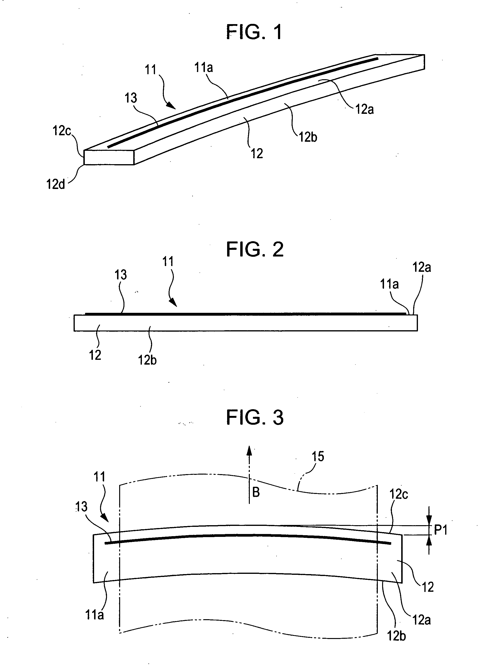
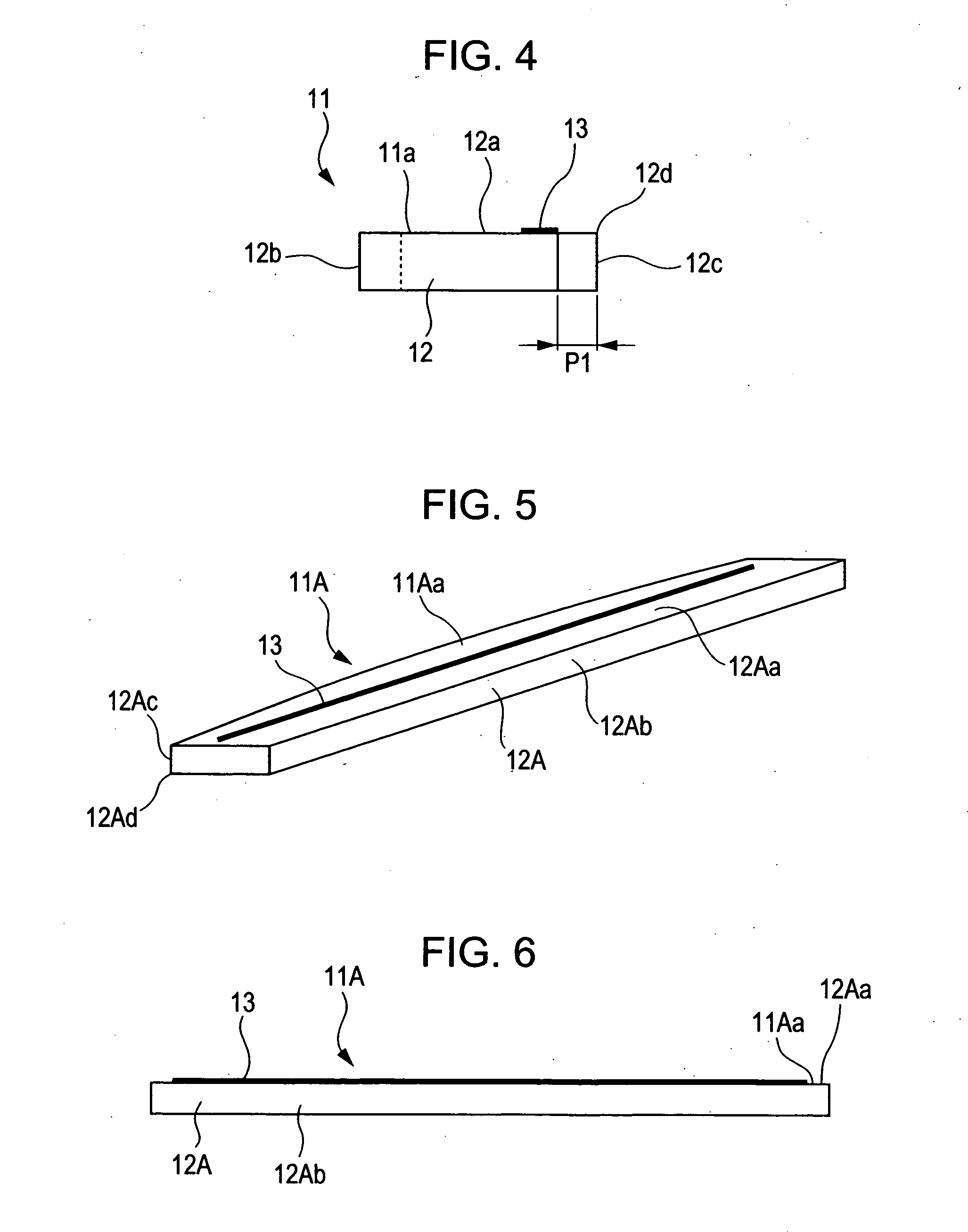
[0052] FIGS. 1 to 4 are respectively a perspective view, an elevational view, a plan view, and a right side view of an essential part of a line-thermal head 11 according to the present invention,.

[0053] As shown in FIGS. 1 to 4, the line thermal head 11 according to the present embodiment includes a substantially flat substrate 12 and a plurality of heating elements 13 for partially melting ink of an ink ribbon 15 indicated by an imaginary line in FIG. 3. The plurality of heating elements 13 is disposed on an upper surface 12a of the substrate 12, serving as a printing surface 11a of the line thermal head 11.

[0054] The substrate 12 has end surfaces 12b and 12c on its both longitudinal sides, which lie respectively upstream and downstream with respect to the traveling direction of the ink ribbon 15 shown by the imaginary arrow B indicated in FIG. 3 (the same direction as the paper feeding direction or the transporting direction of a paper sheet) and which extend substantially parall...

second embodiment

[0065] FIGS. 5 to 8 are respectively a perspective view, an elevational view, a plan view, and a right side view of an essential part of a line-thermal head 11A according to the present invention.

[0066] The line thermal head 11A according to the present embodiment has a structure in which an edge 12Ad of an upper surface 12Aa of a substrate 12A, lying downstream with respect to the traveling direction of the ink ribbon 15, is formed so as to have a curved shape projecting most downstream with respect to the traveling direction of the ink ribbon 15 at its widthwise central portion.

[0067] More particularly, the line thermal head 11A according to the present embodiment has a structure in which, upon forming the substrate 12A so as to have a predetermined shape, each of an end surface 12Ac and the edge 12Ad of the substrate 12A, lying downstream with respect to the traveling direction of the ink ribbon 15, is formed with a mechanical process such as a dicing process so as to have a cur...

third embodiment

[0071] FIGS. 9 to 12 are respectively a perspective view, an elevational view, a plan view, and a right side view of an essential part of a line thermal head 11B according to the present invention.

[0072] The line thermal head 11B according to the present embodiment has a structure in which each of an end surface 12Bc and an edge 12Bd of an upper surface 12Ba of a substrate 12B, lying downstream with respect to the traveling direction of the ink ribbon 15, is formed so as to have a curved shape projecting most downstream with respect to the traveling direction of the ink ribbon 15 at its widthwise central portion, and also, the entire upper surface 12Ba is formed so as to have a curved surface projecting most toward the ink ribbon 15 at its widthwise central portion.

[0073] An projection amount P1 from both ends of each of the end surface 12Bc and the edge 12Bd of the upper surface 12Ba lying downstream with respect to the traveling direction of the ink ribbon 15 and a convex amount ...


PUM


Abstract

In order to improve the traveling stability of an ink ribbon, a thermal head having a structure in which an edge of one surface of a substrate, lying downstream with respect to the traveling direction of an ink ribbon, is formed so as to have a curved shape projecting most downstream with respect to the traveling direction of the ink ribbon at the widthwise central portion of the ink ribbon or a thermal-transfer line printer having a structure in which a separation member separating the ink ribbon from a paper sheet and a tension-exerting section are independently formed from each other is provided.

Description

BACKGROUND OF THE INVENTION [0001] 1. Field of the Invention [0002] The present invention relates to a line thermal head suitable for use in improving the traveling stability of an ink ribbon and also to a thermal-transfer line printer. [0003] 2. Description of the Related Art [0004] A known thermal-transfer line printer has a structure in which a line thermal head having a length corresponding to the longitudinal or horizontal printing range of a sheet of paper (hereinafter, referred to as a paper sheet) serving as a recording medium is abutted against a platen through a wide ink ribbon such as an ink film or an ink sheet and the paper sheet, and, when a plurality of heating elements arranged so as to correspond to the printing width (recording width) in the longitudinal direction of the line thermal head is selectively driven and heated, ink of the ink ribbon is transferred to the paper sheet so as to achieve printing (recording) on the basis of printing information (recording inf...

Claims


Application Information

Patent Timeline
IPC IPC(8): B41J2/335
CPCB41J2/335
Inventor TERAO, HIROTOSHIWAUKE, TOMOKOHOSHINO, HISASHISASAKI, TSUNEYUKIMARUYAMA, TAKAHITO
Owner ALPS ALPINE CO LTD
Why Eureka
Try Eureka