
Color reproduction system for making color display of four or more primary colors based on input tristimulus values

a color reproduction system and input tristimulus technology, applied in the field of color reproduction systems, can solve the problems of inability to reproduce all input colors, method cannot guarantee the obtaining of a solution in which all primary-color signals can be solved, reproducible input colors cannot be accurately reproduced, etc., to achieve the effect of accurate color reproduction

Inactive Publication Date: 2005-07-28
OLYMPUS CORP
View PDF14 Cites 7 Cited by
  • Summary
  • Abstract
  • Description
  • Claims
  • Application Information

AI Technical Summary

Benefits of technology

The present invention provides a color reproduction system that can accurately reproduce colors in the whole color reproduction area. This is achieved by a color converting unit that includes an area deciding section and a color image signal calculating section. The area deciding section decides a color conversion area to which input three-primary color signals belong in a three-dimensional color space, while the color image signal calculating section converts the input three-primary color signals into color image signals of respective primary colors based on color conversion parameters corresponding to the decided area. Additionally, the color converting unit may also include a look-up table for outputting a table data corresponding to the input three-primary color signals, an interpolation coefficient calculating section for calculating an interpolation coefficient corresponding to a data interval of the look-up table, and an interpolation calculating section for calculating an input signal to the color image display unit based on the table data and the interpolation coefficient.

Problems solved by technology

However, it is not possible to reproduce all the input colors as this method does not basically take into account a color reproduction area in a luminance direction of the multi-primary color display.
Further, according to the color conversion method of the second example disclosed in Jpn. Pat. Appln. KOKAI Publication No. 6-261332, the method does not guarantee the obtaining of a solution in which all the primary-color signals are positive.
Therefore, in some cases, reproducible input colors cannot be reproduced accurately.

Method used


Image

  • Color reproduction system for making color display of four or more primary colors based on input tristimulus values
  • Color reproduction system for making color display of four or more primary colors based on input tristimulus values
  • Color reproduction system for making color display of four or more primary colors based on input tristimulus values

Examples


first embodiment

(First Embodiment)

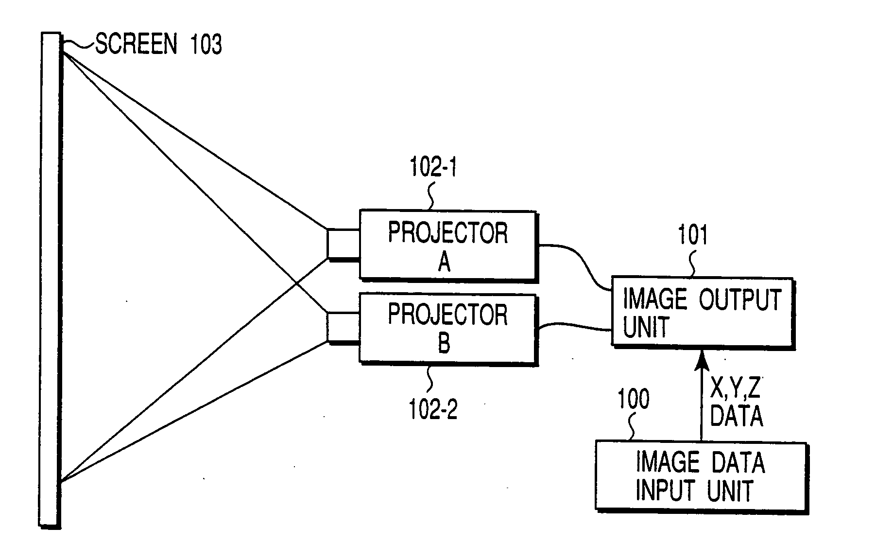
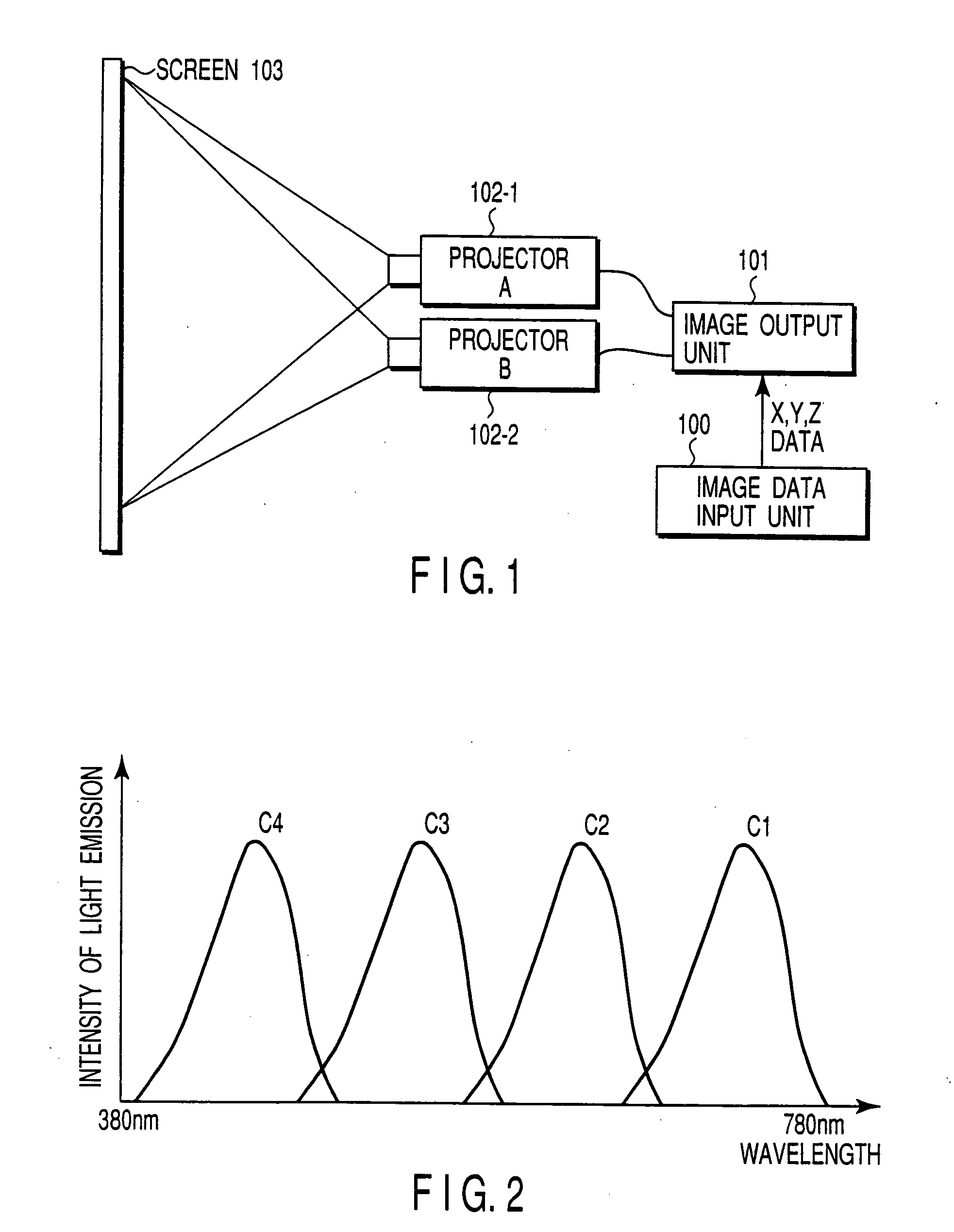
[0042]FIG. 1 is a diagram showing a schematic structure of a multi-primary color projector system as a color reproduction system relating to a first embodiment of the present invention. An image data input unit 100 takes in color image data from a digital camera, a color scanner or the like. The image data input unit 100 converts this color image data into image data (input tristimulus values) consisting of X, Y and Z of the CIE1931 color display system for each pixel by using spectral sensitivity characteristics-of the input unit that has taken the color image data and illumination data of the data input time. The image data input unit 100 then outputs the converted data to an image output unit 101.

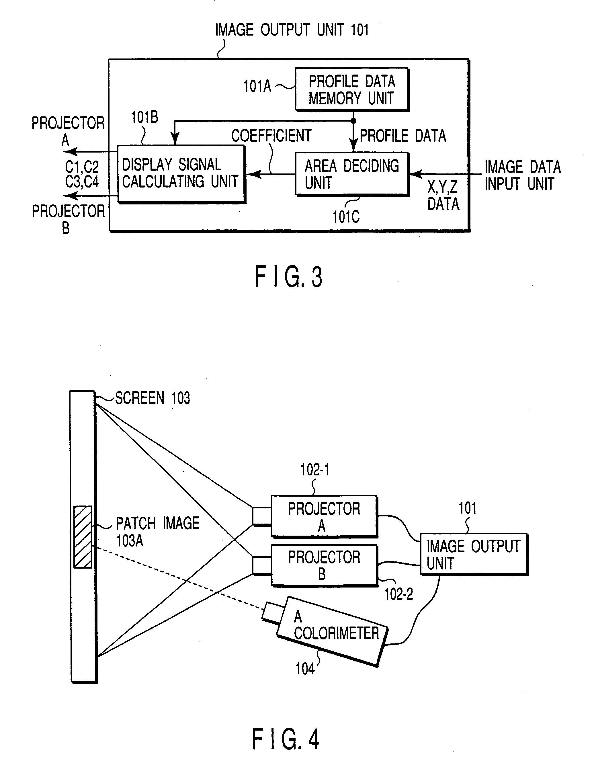
[0043] The image output unit 101 converts the X, Y and Z data into input signals C1 and C2 to be applied to a projector A (102-1) and input signals C3 and C4 to be applied to a projector B (102-2), and outputs these signals to these corresponding projectors. The projec...

second embodiment

(Second Embodiment)

[0056] A second embodiment of a color reproduction system according to the present invention will be explained. Structures other than that of the image output unit are similar to those of the first embodiment, and their explanation will be omitted. An image output unit 101′ of the second embodiment consists of a look-up table preparing unit 101D, a look-up table 101E, an interpolation coefficient calculating unit 101F, and an interpolation calculating unit 101G, as shown in FIG. 7. X, Y and Z data supplied from an image data input unit 100 are input to the look-up table 101E and to the interpolation coefficient calculating unit 101F.

[0057] The look-up table 101E outputs table data corresponding to the X, Y and Z data that have been input to the interpolation calculating unit 101G. The interpolation coefficient calculating unit 101F calculates an interpolation coefficient corresponding to a data interval of data from the look-up table 101E by using the input X, Y ...

third embodiment

(Third Embodiment)

[0067] A third embodiment of a color reproduction system according to the present invention will be explained. In the third embodiment, operation of the image output unit is similar to that of the image output unit 101 explained in the first embodiment except the processing of the area deciding unit 101C and the display signal calculating unit 101B. Therefore, the explanation of the similar units will be omitted here.

[0068] In the third embodiment, a color reproduction area has been divided into a plurality of tetrahedrons in advance. An area deciding unit decides an area that includes input X, Y and Z data from out of all the divided areas. The area deciding unit calculates a linear signal from the X, Y and Z data and the profile data corresponding to the divided area, and outputs the calculated signal to a display signal calculating unit of the third embodiment. A display signal calculating unit corrects the gradation of the linear signal and calculates a displa...


PUM


Abstract

A display apparatus includes a color image projection unit and a screen. The color image projection unit includes a converter which receives image signals of three primary colors, and converts the received image signals of three primary colors into image signals of four or more primary colors, and a color image projector which includes a plurality of image projection devices having respective primary colors, and which receives the image signals of four or more primary colors, and projects the received image signals of four or more primary colors onto the screen. The color image projector is capable of physically adjusting positions of the image signals of four or more primary colors, which are projected onto the screen such that the positions of the image signals are coincident with each other.

Description

CROSS-REFERENCE TO RELATED APPLICATIONS [0001] This application is a division of application Ser. No. 10 / 465,693 filed Jun. 19, 2003, which in turn is a division of application Ser. No. 09 / 577,923 filed May 24, 2000 (now U.S. Pat. No. 6,633,302 issued Oct. 14, 2003), which is based upon and claims the benefit of priority from the prior Japanese Patent Application No. 11-146520, filed May 26, 1999, the entire contents of each of which are incorporated herein by reference.BACKGROUND OF THE INVENTION [0002] The present invention relates to a color reproduction system, and relates, more particularly, to a color reproduction system for obtaining an input color image signal for displaying desired colors in a color image display unit capable of displaying a color image of at least four primary colors. [0003] There have been widely used various display units such as CRT displays, liquid crystal displays, liquid crystal projectors, etc. as means for reproducing digital color images that have...

Claims


Application Information

Patent Timeline
Patent Type & Authority Applications(United States)
IPC IPC(8): G06T1/00G09G3/00H04N9/64G09G5/00G09G5/02G09G5/06H04N1/46H04N1/60H04N9/31
CPCG09G3/001H04N9/3197H04N9/3105G09G5/02
Inventor OHSAWA, KENROOHYAMA, NAGAAKIYAMAGUCHI, MASAHIROAJITO, TAKEYUKI
Owner OLYMPUS CORP
Learn More