Coding device, decoding device, coding method, and decoding method

Active Publication Date: 2005-07-28
III HLDG 12 LLC
View PDF14 Cites 102 Cited by
  • Summary
  • Abstract
  • Description
  • Claims
  • Application Information

AI Technical Summary

Benefits of technology

[0011] It is an object of the present invention to provide a coding apparatus, decoding apparatus, coding method, and decoding method that enable high-quality c

Problems solved by technology

However, when coding is performed using a speech coding method on a signal in which a speech signal is predominant and music or environmental sound is superimposed in the background, there is a problem in that, due to the background music or environmental sound, not only the background signal but also the speech signal degrades, and overall quality deteriorates.
This problem occurs because speech coding methods are based on a method specialized toward a CELP speech model

Method used


Image

  • Coding device, decoding device, coding method, and decoding method
  • Coding device, decoding device, coding method, and decoding method
  • Coding device, decoding device, coding method, and decoding method

Examples


Example

Embodiment 1

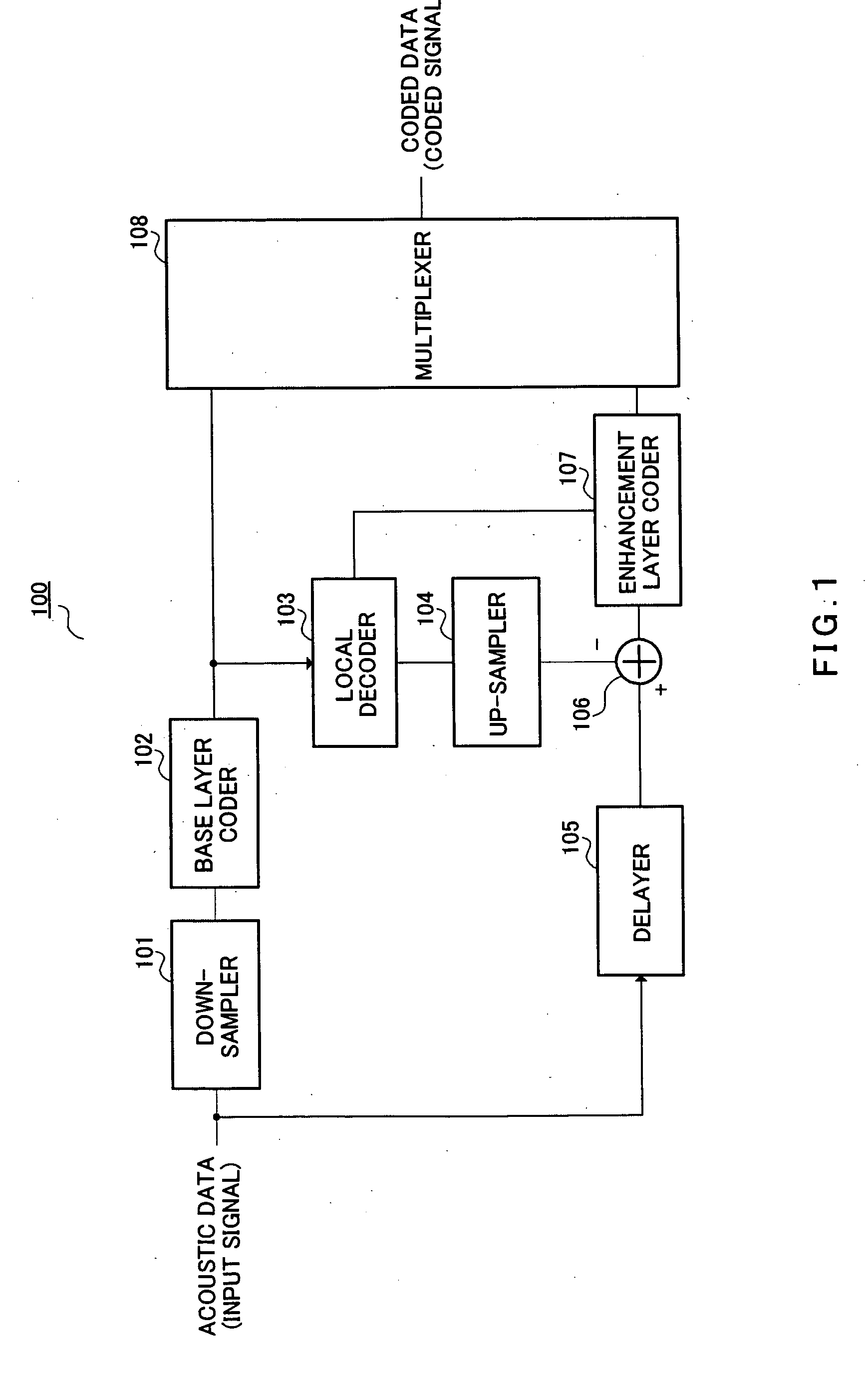
[0059]FIG. 1 is a block diagram showing the configuration of a signal processing apparatus according to Embodiment 1 of the present invention. Signal processing apparatus 100 in FIG. 1 mainly comprises a down-sampler 101, base layer coder 102, local decoder 103, up-sampler 104, delayer 105, subtracter 106, enhancement layer coder 107, and multiplexer 108.

[0060] Down-sampler 101 down-samples the input signal sampling rate from sampling rate FH to sampling rate FL, and outputs the sampling rate FL acoustic signal to base layer coder 102. Here, sampling rate FL is a lower frequency than sampling rate FH.

[0061] Base layer coder 102 encodes the sampling rate FL acoustic signal and outputs the coding information to local decoder 103 and multiplexer 108.

[0062] Local decoder 103 decodes the coding information output from base layer coder 102, outputs the decoded signal to up-sampler 104, and outputs parameters obtained from the decoded result to enhancement layer coder 107. ...

Example

Embodiment 2

[0078] In this embodiment an example is described in which, of the parameters decoded by local decoder 103 of Embodiment 1, LPC coefficients indicating the input signal spectrum is used as a parameter utilized by enhancement layer coder 107.

[0079] A signal processing apparatus of this embodiment performs coding using CELP in base layer coder 102 in FIG. 1, and performs coding using LPC coefficients indicating the input signal spectrum in enhancement layer coder 107.

[0080] A detailed description of the operation of base layer coder 102 will first be given, followed by a description of the basic configuration of enhancement layer coder 107. The “basic configuration” mentioned here is intended to simplify the descriptions of subsequent embodiments, and denotes a configuration that does not use local decoder 103 coding parameters. Thereafter, a description is given of enhancement layer coder 107, which uses the LPC coefficients decoded by local decoder 103, this being a f...

Example

Embodiment 3

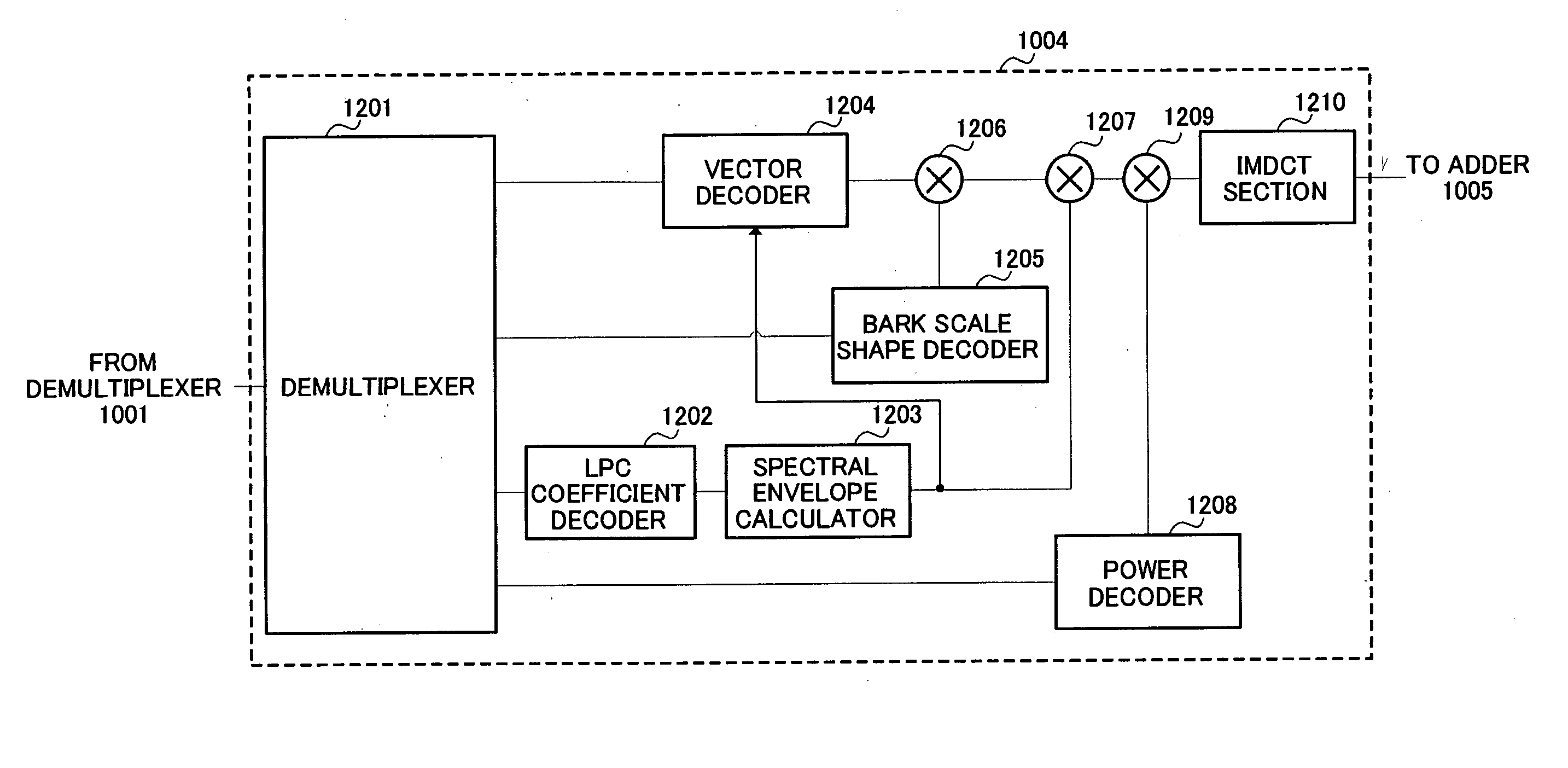
[0142]FIG. 8 is a block diagram showing the configuration of the enhancement layer coder of a signal processing apparatus according to Embodiment 3 of the present invention. Parts in FIG. 8 identical to those in FIG. 5 are assigned the same reference numerals as in FIG. 5 and detailed descriptions thereof are omitted.

[0143] Enhancement layer coder 107 in FIG. 8 differs from the enhancement layer coder in FIG. 5 in being provided with a spectral fine structure calculator 801, calculating spectral fine structure using a pitch period coded by base layer coder 102 and decoded by local decoder 103, and employing that spectral fine structure in spectrum normalization and vector quantization.

[0144] Spectral fine structure calculator 801 calculates the spectral fine structure from pitch period T and pitch gain β coded in the base layer, and outputs the spectral fine structure to spectrum normalizer 506.

[0145] The aforementioned pitch period T and pitch gain β are actually pa...


PUM


Abstract

A down-sampler 101 down-samples the sampling rate of an input signal from sampling rate FH to sampling rate FL. A base layer coder 102 encodes the sampling rate FL acoustic signal. A local decoder 103 decodes coding information output from base layer coder 102. An up-sampler 104 raises the sampling rate of the decoded signal to FH. A subtracter 106 subtracts the decoded signal from the sampling rate FH acoustic signal. An enhancement layer coder 107 encodes the signal output from subtracter 106 using a decoding result parameter output from local decoder 103.

Description

TECHNICAL FIELD [0001] The present invention relates to a coding apparatus, decoding apparatus, coding method, and decoding method that perform highly efficient compression coding of an acoustic signal such as an audio signal or speech signal, and more particularly to a coding apparatus, decoding apparatus, coding method, and decoding method that are suitable for scalable coding and decoding that enable decoding of audio or speech even from a part of coding information. BACKGROUND ART [0002] A sound coding technology that compresses an audio signal or speech signal at a low bit rate is important for efficient utilization of radio in mobile communications and recording media. Methods for speech coding, in which a speech signal is coded, include G726 and G729 standardized by the ITU (International Telecommunication Union). These methods encode narrowband signals (300 Hz to 3.4 kHz), and enable high-quality coding at bit rates of 8 kbits / s to 32 kbits / s. [0003] Standard methods for wid...

Claims


Application Information

Patent Timeline
IPC IPC(8): G10L19/24
CPCG10L19/24
Inventor OSHIKIRI, MASAHIRO
Owner III HLDG 12 LLC
Why Eureka
Try Eureka