
Method for adaptive image region partition and morphologic processing

a morphologic processing and image region technology, applied in image enhancement, image analysis, instruments, etc., can solve the problems of complex shapes, time-consuming, and shape-dependent processing time of these methods, and achieve fast image region partitioning, predictable processing time, and processing speed. the effect of mainly

Active Publication Date: 2005-07-28
LEICA MICROSYSTEMS CMS GMBH
View PDF4 Cites 27 Cited by
  • Summary
  • Abstract
  • Description
  • Claims
  • Application Information

AI Technical Summary

Benefits of technology

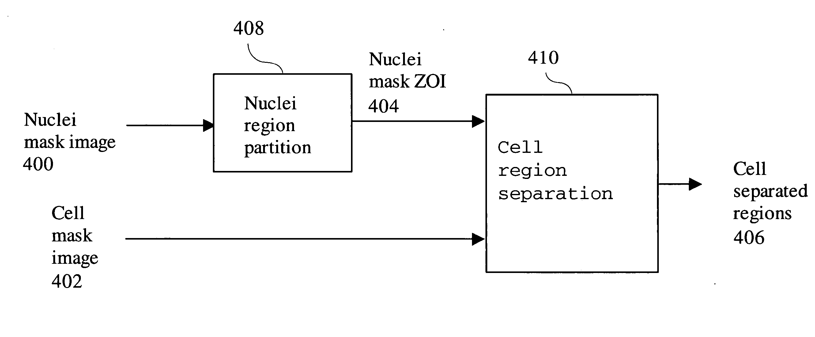
[0008] This invention provides a method for adaptive image region partition and morphologic processing. The partition is computed sequentially by a two-pass procedure similar to distance transformation. In addition to the shortest distance, the method tracks, propagates, and updates the component label where a pixel's shortest distance is derived. The method is very fast and the processing time is predictable and is component shape independent. It requires O(N2) time for an N by N image and is ideal for a use in a general purpose CPU. It could adaptively apply a distance metric depending on component characteristics. It enables adaptive morphological processing that allows adaptive adjustment of the structuring element size and shape according to characteristics of the components. Furthermore, the method enables adaptive integration of multiple channel information in cell analysis.
[0009] The primary objective of the invention is to perform fast image region partitioning. A secondary objective is to achieve processing speed mostly independent of component shape. Another objective of the invention is to adaptively apply a distance metric dependent on component characteristics. The fourth objective is to provide adaptive morphologic processing that allows adaptive adjustment of the structuring element size and shape according to the characteristics of the components. The fifth objective of the invention is to provide adaptive integration of multiple channel information in cell analysis for improved image measurement accuracy. The sixth objective of the invention is to reduce cost and increase availability by facilitating real time applications using general purpose CPUs.
[0010] A fast image region parti

Problems solved by technology

The method is very fast.
However, the skeletonization requires iterative thinning or similar techniques.
The processing time of these methods is shape dependent and sometimes time consuming for complex shapes.
The recursive morphology operation is not efficient for a general purpose computer and is time consuming for complex shapes.
This is often not the case in practical applications.
In this case, it is disadvantageous to determine ZOI using the same distance metric across all cell types since large and small cells will be divided equally.
The same limitation exists in morphological dilation or erosion operations and their combinations, such as opening and closing.

Method used


Image

  • Method for adaptive image region partition and morphologic processing
  • Method for adaptive image region partition and morphologic processing
  • Method for adaptive image region partition and morphologic processing

Examples


Embodiment Construction

I. Distance Transform

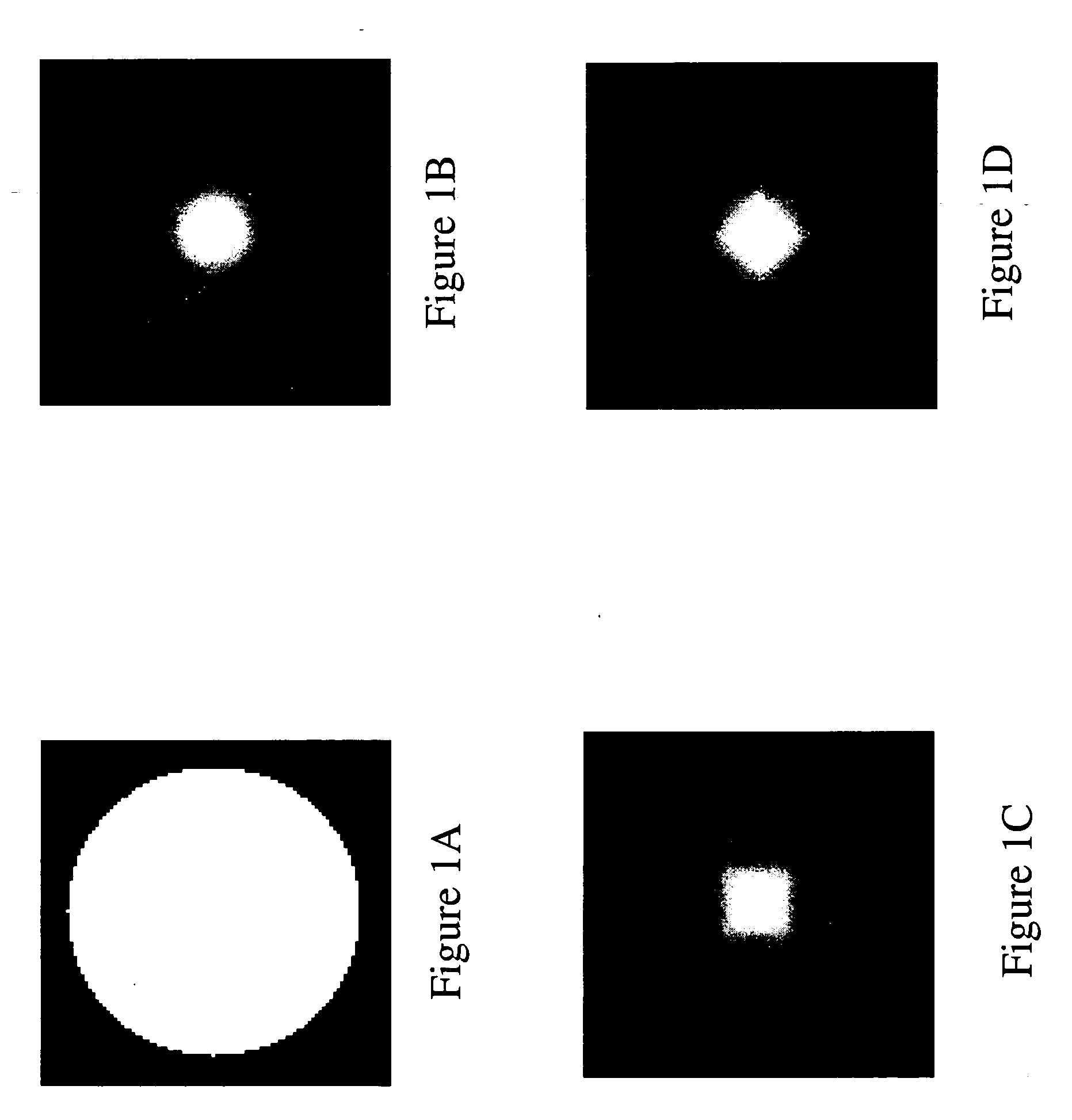
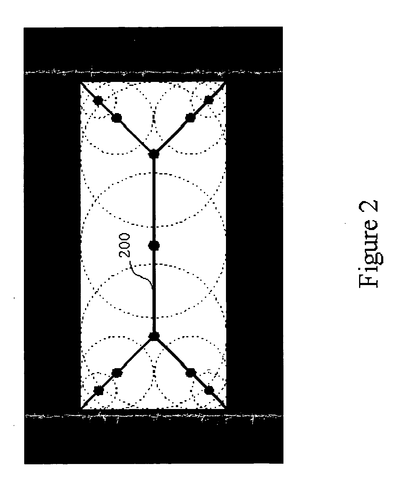
[0028] Given an image I, the foreground distance transform assigns each foreground pixel the shortest distance between the pixel and a background pixel. Conversely, the background distance transform assigns each background pixel the shortest distance between the pixel and a foreground pixel.

[0029] The distance transform is computed sequentially by a two-pass method. The first (forward) pass scans in a left-right top-bottom raster scan order. The second (backward) pass scans in a reverse right-left bottom-top order. In the first pass for a foreground distance transform, the output U(x,y) at pixel position (x,y) is determined by the value of input image I and the values at previously computed positions of U by U⁡(x,y)={min(i,j)∈NB⁡(x,y)⁢{U⁡(i,j)+l⁡(i,j)};∀I⁡(x,y)∈foreground0;∀I⁡(x,y)∈background

[0030] In one embodiment, the boundary condition is handled by setting U(x,−1)=0 and U(−1,y)=0. NB(x,y) is the backward neighbors of the pixel (x,y). The backward neighbor...


PUM


Abstract

A fast image region partition method receives a component labeled image and performs a two pass Zone Of Influence (ZOI) creation method to create a Zone Of Influence (ZOI) image. The two pass ZOI creation method performs a first pass scan to create a first pass intermediate distance image and a shortest distance component label image. It then performs a second pass scan using the first pass intermediate distance image and the shortest distance component label image to create a background distance transform image and a updated shortest distance component label image. An adaptive image region partition method receives a component labeled image and performs an adaptive two pass ZOI creation method to create an adaptive ZOI image. The distance lengths of the two pass adaptive ZOI creation method depend on their associated component labels. An adaptive cell segmentation method receives a nuclei mask image and a cell mask image. It performs adaptive nuclei region partition using the nuclei mask image to create adaptive nuclei mask ZOI. An adaptive cell region separation method uses the cell masks and the adaptive nuclei mask ZOI to generate adaptive cell separated regions. An adaptive dilation method receives an image and performs an adaptive background distance transform to create an adaptive background distance transform image. A threshold is applied to the adaptive background distance transform image to generate adaptive dilation image output. An adaptive erosion method receives an image and performs an adaptive foreground distance transform to create an adaptive foreground distance transform image. A threshold is applied to the adaptive foreground distance transform image to generate adaptive erosion image output.

Description

TECHNICAL FIELD [0001] This invention relates to a method for adaptive image region partition and morphologic processing. BACKGROUND OF THE INVENTION [0002] Given an image that consists of a plurality of component regions, its image can be partitioned into zones of influence (ZOI). In the ZOI image, each pixel is associated with a component label. The component (foreground) pixels in the component regions are labeled by their component labels. The non-component (background) pixels are labeled by the labels of the component that is closest to the pixels. [0003] ZOI is a powerful tool to integrate results of multiple images acquired from different aspects of the same objects of interest. In one typical application scenario, the component regions are detected from one image or one detection mode. The component regions are used to form the ZOI. The ZOI is then used to condition the detection or perform measurements of other images or other detection modes. One application example is cel...

Claims


Application Information

Patent Timeline
IPC IPC(8): G06K9/00G06K9/34G06T5/00
CPCG06K9/0014G06K9/4638G06T7/0081G06T7/0091G06T7/60G06T2207/30024G06T2207/20012G06T2207/20041G06T2207/20044G06T2207/20141G06T2207/10056G06T7/11G06T7/155G06T7/187G06V20/695G06V10/457
Inventor LEE, SHIH-JONG J.PHAN, TUAN
Owner LEICA MICROSYSTEMS CMS GMBH
Learn More