Supercharge Your Innovation With Domain-Expert AI Agents!

Bulkhead mountable optoelectronic device

a technology of optoelectronic devices and bulkheads, which is applied in the direction of electrical apparatus construction details, electrical apparatus casings/cabinets/drawers, instruments, etc., to achieve the effects of convenient installation, low cost, and low weigh

Inactive Publication Date: 2005-07-28
STRATOS INT
View PDF23 Cites 4 Cited by
  • Summary
  • Abstract
  • Description
  • Claims
  • Application Information

AI Technical Summary

Benefits of technology

The integrated design results in a lighter, more reliable, and cost-effective optoelectronic device that is easier to install, reducing optical power losses and improving space efficiency by eliminating unnecessary connectors and adapters.

Problems solved by technology

Furthermore, such goals must be met while operating within a limited financial budget.

Method used


Image

  • Bulkhead mountable optoelectronic device
  • Bulkhead mountable optoelectronic device
  • Bulkhead mountable optoelectronic device

Examples


Embodiment Construction

[0029] Referring now to the drawings, wherein like reference numerals designate identical or corresponding parts throughout the several views, and more particularly to FIGS. 1-3 and 5-11 thereof, an embodiment of the present invention is a device or optoelectronic device 10 which is displayed therein.

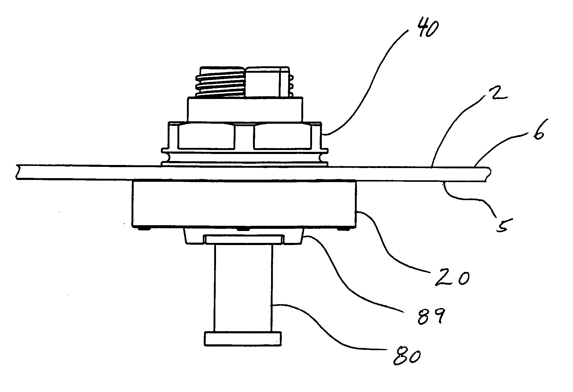
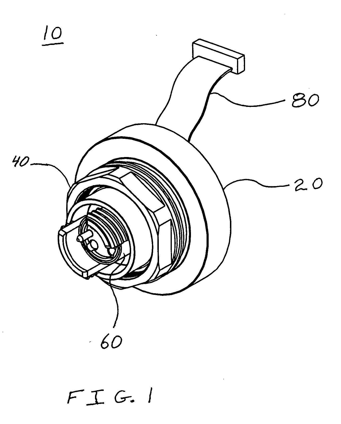
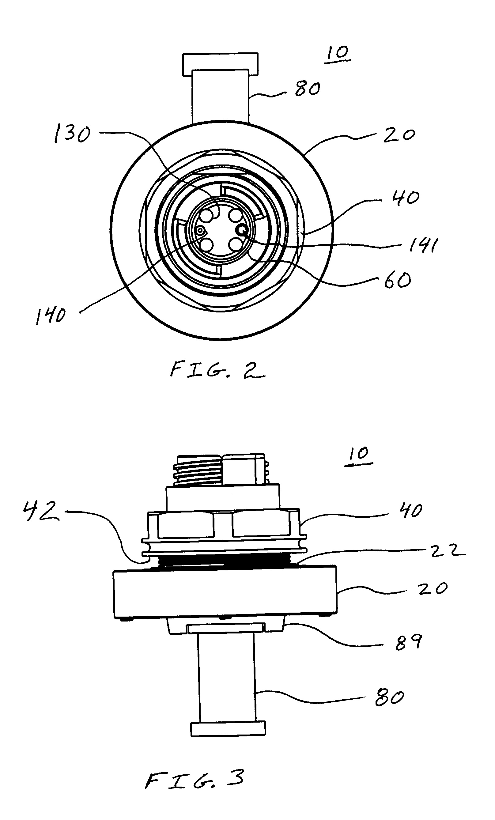
[0030]FIG. 1 is a perspective view of the optoelectronic device 10. The optoelectronic device 10, as shown in FIG. 1, includes sleeve 20, a panel nut 40, and an insert body 60. Also shown in FIG. 1 is a ribbon cable 80. The insert body 60 is insertable into an aperture 28 (see FIG. 10) of the sleeve 20. The panel nut 40 is mounted on the sleeve 20 via threaded surfaces. The ribbon cable 80 is attachable to an electrical connector or header 89 (see FIG. 3) of the optoelectronic device 10. The free end of the ribbon cable 80 is adapted to attach to another electrical connector, such as may be located on a remotely located and secured mother board, so that electrical power can flow to the...


PUM


Abstract

The optoelectronic device includes a sleeve, an insert body, a ferrule, a lens, an optical subassembly, an electrical connector, a substrate, a cover, and a panel nut. The sleeve includes seating surface, an aperture, and thread form. The panel nut has a thread form, and a seating surface. The thread form of the panel nut is complimentary to the thread form of the sleeve so that the panel nut is removeably mountable on the sleeve. In a mounted position, the thread form of the panel nut fully engages the thread form of the sleeve so that the seating surface of the of the panel nut contacts a first one surface of a bulkhead and the seating surface of the sleeve contacts another surface of the bulkhead so that the device is securely mounted to the bulkhead.

Description

BACKGROUND OF THE INVENTION [0001] 1. Field of the Invention [0002] The present invention pertains to optoelectronic devices. The invention more particularly concerns an optoelectronic device that is mountable to a bulkhead. [0003] 2. Discussion of the Background [0004] An optoelectronic device utilizes at least one optical subassembly. The optical subassembly can be an optoelectronic receiver or an optoelectronic transmitter. An optoelectronic transmitter receives electrical signals, converts the electrical signals to light signals, and then transmits the light signals. An optoelectronic receiver receives light signals, converts the light signals to electrical signals, and then transmits the electrical signals. A transceiver is an optoelectronic device which has at least one optoelectronic receiver and at least one otpoelectronic transmitter. [0005] In order to pass optical signals through a bulkhead, an optical bulkhead connector is employed. The optical bulkhead connector employs...

Claims


Application Information

Patent Timeline
Patent Type & Authority Applications(United States)
IPC IPC(8): G02B6/36G02B6/38G02B6/42H05K5/00H05K5/04H05K5/06
CPCG02B6/3894G02B6/4292G02B6/4248
Inventor BOHLIN, JOHNSCHARF, ROBERT
Owner STRATOS INT
Features
  • R&D
  • Intellectual Property
  • Life Sciences
  • Materials
  • Tech Scout
  • Unparalleled Data Quality
  • Higher Quality Content
  • 60% Fewer Hallucinations
Learn More