Method of producing battery plates

a technology of battery plate and plate plate, which is applied in the manufacture of final products, cell components, basic electric elements, etc., can solve the problems of low formation efficiency of positive plate, high formation charge, and inefficient charging of resulting batteries assembled with such plates, so as to improve contact, increase the formation efficiency of battery and battery cycle life, and improve the effect of adhesion

Inactive Publication Date: 2005-07-28
CPS TECH HLDG LLC
View PDF57 Cites 55 Cited by
  • Summary
  • Abstract
  • Description
  • Claims
  • Application Information

AI Technical Summary

Benefits of technology

[0027] The foregoing needs in the art and the foregoing objects are achieved by a method of forming battery grids or battery plates that includes the step of mechanically reshaping or refinishing battery grid wires to improve contact between the battery paste and the grid wires. As a result of this reshaping or refinishing of the grid wires, paste adhesion is increased thereby increasing battery formation efficiency and battery cycle life.

Problems solved by technology

A low formation efficiency of positive plates requires a high formation charge.
Inefficient charging also leads to deficiencies in the resulting batteries assembled with such plates.
Typically, the initial capacity (performance) of the battery is low if the battery is not completely formed, requiring additional cycling to reach specific performance values.
It is well known that lead-acid batteries will eventually fail in service through one or more of several failure modes.
Among these failure modes is failure due to corrosion of the grid surface.
Electrochemical action corrodes the grid surface and reduces the adhesion between the active material and the grid.
In most instances, failure of the battery occurs when the grids are no longer able to provide adequate structural support or current flow due to the separation of the active material from the grid.
While these methods may provide satisfactory solutions to the problem of inadequate paste adhesion, they do have certain disadvantages.
It can be appreciated that the additional process steps and materials required in these methods can significantly increase the cost of manufacturing the battery grids.
As a result, certain battery manufacturers may be reluctant to incorporate these methods into a production facility.
However, it has been discovered that another source of the problem of inadequate paste adhesion may be the configuration of the grid.
With rectangular wires, on the other hand, it is much more difficult to make good contact between the battery paste and the surface of the wire moving in a direction perpendicular to the direction in which the paste is applied because the flow of paste must change in a 90 degree step.
This type of plate is weak and the paste will fall off easily.
Because of a lack of contact between the paste and the grid, a battery made with this type of plate is much more difficult to form, performs poorly in certain reserve capacity tests, and does not exhibit satisfactory cycle life.

Method used


Image

  • Method of producing battery plates
  • Method of producing battery plates
  • Method of producing battery plates

Examples


example 1

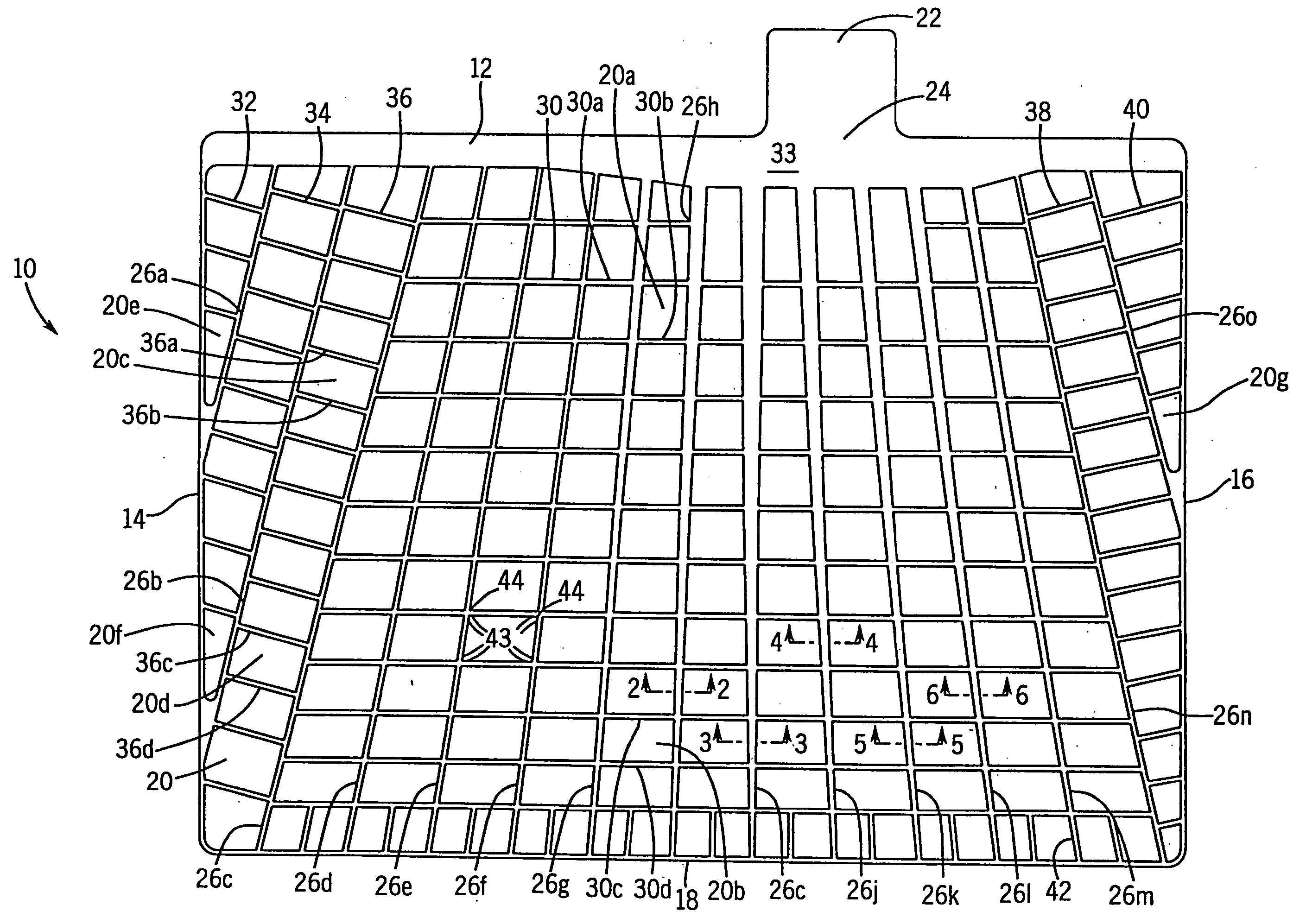
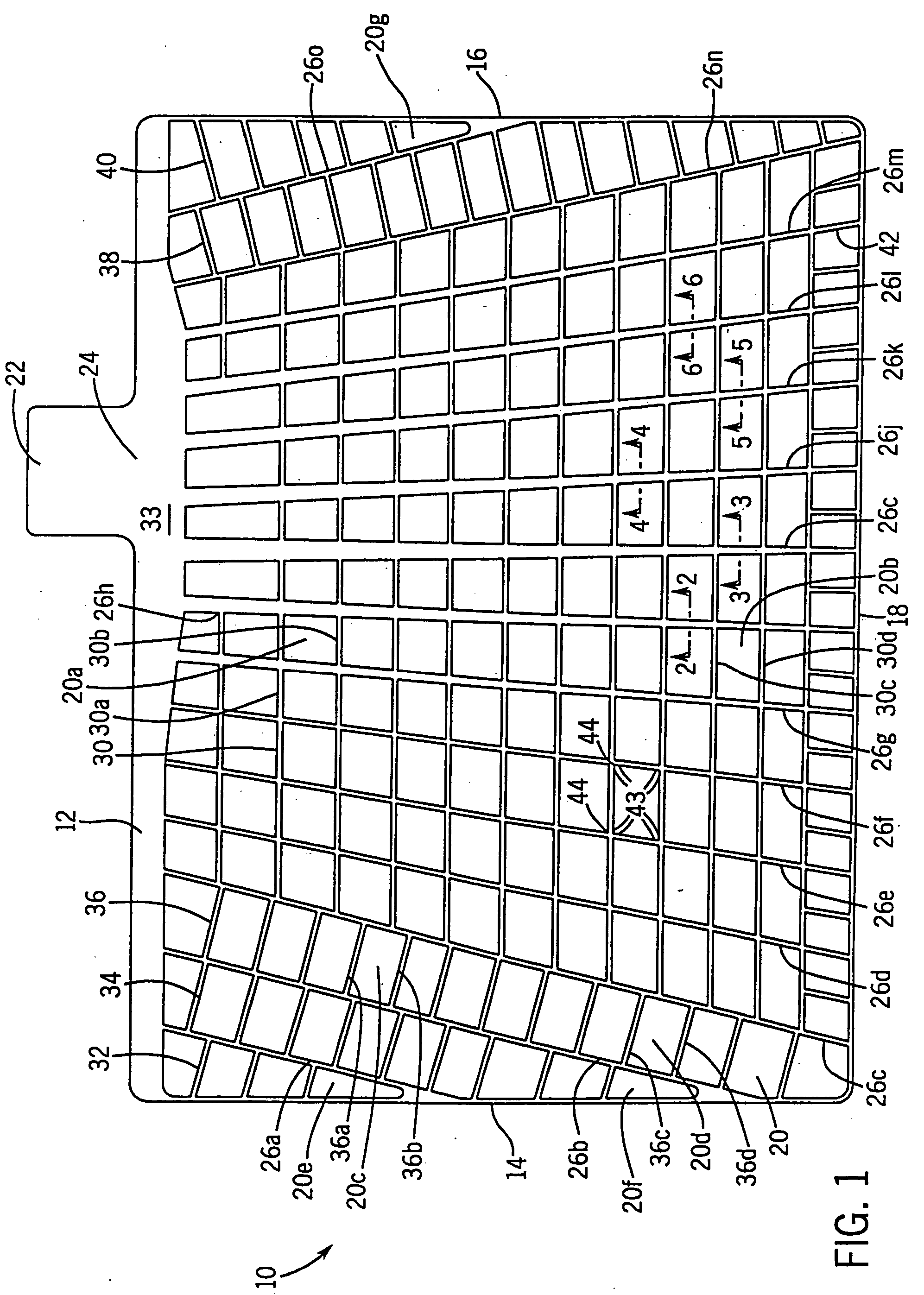
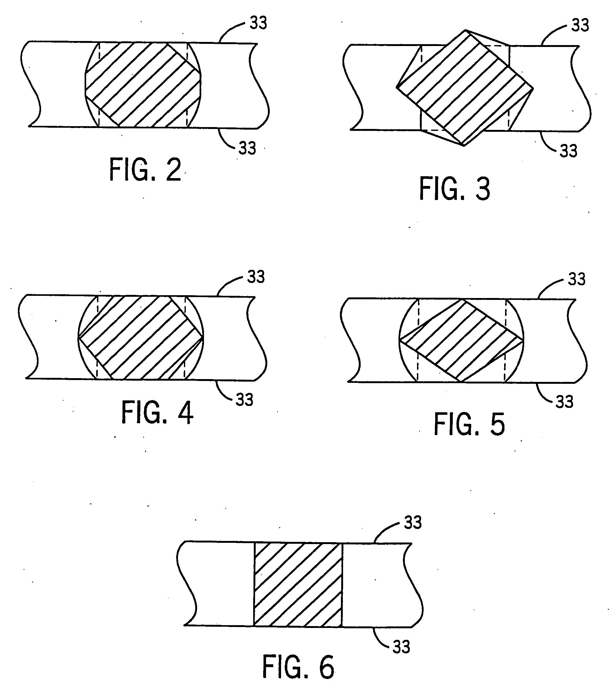
[0068] A conventional stamped battery grid with grid wires having a rectangular cross-section and smooth surfaces (as depicted in FIGS. 1 and 6) was pasted with a conventional positive paste for lead acid batteries and then cured. The cured plate was sectioned with a cutting wheel in a direction transverse to the planar surface of the plate, polished, and photographed. The photograph is shown in FIG. 7. As FIG. 7 shows, the cured plate exhibits gaps 70 at the paste 72 / grid wire 73 interfaces, and the gaps extend into the bulk paste as cracks 71.

EXAMPLE 1(a)

[0069] A second conventional stamped battery grid identical to the grid used in Example 1 was substantially modified by rotating a major portion of grid wires by 45 degrees. (This version of a grid is depicted in FIGS. 1 and 3.) The modified grid was then pasted with a conventional positive paste for lead acid batteries and cured. The cured plate was sectioned with a cutting wheel in a direction transverse to the planar surface ...

example 1 (

EXAMPLE 1(c)

[0071] A fourth conventional stamped battery grid identical to the grid used in Example 1 was substantially modified by stamping the grid wires to form an octagonal shaped cross-section. (This version of a grid is depicted in FIGS. 1 and 2.) The modified grid was then pasted with a conventional positive paste for lead acid batteries and cured. The cured plate was sectioned with a cutting wheel in a direction transverse to the surface of the plate, polished, and photographed. The photograph is shown in FIG. 10. It can be seen from FIG. 10 (wherein the grid wire is designated at 100 and the paste is designated at 101) that the plate prepared using the modified grid of Example 1(c) exhibited improved paste adhesion compared to the plate prepared using the grid of Example 1 (FIG. 7) and that the plate prepared using the modified grid of Example 1(c) exhibited a reduced number of cracks.

example 2

[0072] Vibration weight loss is a very good measure to evaluate the strength of a battery plate. In order to demonstrate the effectiveness of the present invention, two battery plates were prepared. The first battery plate was prepared using the procedure of Example 1, and the second battery plate was prepared using the procedure of Example 1(c). The control plate of Example 1 and the plate of the present invention as described as Example 1(c) were then placed on a platform vibrating at a frequency of about 60 hertz with an amplitude of about three millimeters for one minute. The plate weights before and after vibration were compared. On average, the control plates of Example 1 lost 16 times the battery paste that was lost in plates formed in accordance with the present invention of Example 1(c). This test demonstrated that when assembled into battery plates, battery grids manufactured in accordance with the present invention improve paste adhesion between the grid and the paste.


PUM

PropertyMeasurementUnit
frequencyaaaaaaaaaa
temperatureaaaaaaaaaa
shapeaaaaaaaaaa

Abstract

A method of forming battery grids or plates that includes the step of mechanically reshaping or refinishing battery grid wires to improve adhesion between the battery paste and the grid wires. The method is particularly useful in improving the paste adhesion to battery grids formed by a continuous battery grid making process (such as strip expansion, strip stamping, continuous casting) that produces grid wires and nodes with smooth surfaces and a rectangular cross-section. In a preferred version of the method, the grid wires of battery grids produced by a stamping process are deformed such that the grid wires have a cross-section other than the rectangular cross-section produced by the stamping process. The method increases the cycle life of a battery.

Description

BACKGROUND OF THE INVENTION [0001] 1. Field of the Invention [0002] The present invention relates to the modification of battery grids of the type used in lead-acid storage batteries, and more particularly, it relates to a modification of the shape and / or surface finish of the battery grids of a lead-acid storage battery to improve paste adhesion and the service life of the battery. [0003] 2. Description of the Related Art [0004] Lead-acid storage batteries typically comprise several cell elements which are encased in separate compartments of a container containing sulfuric acid electrolyte. Each cell element includes at least one positive plate, at least one negative plate, and a porous separator positioned between each positive and negative plate. The positive and negative plates each comprise a lead or lead alloy grid that supports an electro-chemically active material. The active material is a lead based material (i.e., PbO, PbO2, Pb or PbSO4 at different charge / discharge stages...

Claims


Application Information

Patent Timeline
Patent Type & Authority Applications(United States)
IPC IPC(8): H01M4/73H01M4/74H01M4/84
CPCH01M4/73H01M4/84Y10T29/49108Y10T29/10H01M4/745Y02E60/10Y02P70/50
Inventor SCHAEFFER, CHARLES J.TROXEL, JEFFREY L.TAYLOR, M. ERICKAO, WEN-HONGHANSEN, CHRISTIAN P.CHEN, YU-LINCANTILLON, DAN J.SAUER, BART
Owner CPS TECH HLDG LLC
Why Eureka
Try Eureka