
Delivery device and method of delivery

a delivery device and delivery method technology, applied in the direction of single-unit apparatus, eye treatment, instruments, etc., can solve the problems of other users' difficulty in measuring the dosage and/or manipulating the dropper, and many users' difficulty in using them

Inactive Publication Date: 2005-07-28
MEDICAL INSTILL TECH
View PDF24 Cites 113 Cited by
  • Summary
  • Abstract
  • Description
  • Claims
  • Application Information

AI Technical Summary

Benefits of technology

"The invention is an ophthalmic delivery device that includes a body with a fluid reservoir and a pump, and a nozzle with a valve seat and a valve cover. The valve cover is movable between a closed position and an open position to control the flow of fluid. The device can deliver a metered dose of fluid to the eye with a velocity of less than 10 meters per second. Other embodiments include a dispenser with a compression zone and a spring to pressurize fluid and dispense a metered dosage. The valve seat has a specific design to control the velocity of the fluid. Overall, the invention provides a device for delivering ophthalmic substances with precise control over dosage and velocity."

Problems solved by technology

One drawback associated with such prior art ophthalmic delivery devices is that many users have found them difficult to use.
Some users have difficulty delivering drops into the eyes and instead spill the drops onto other parts of the face.
Other users have difficulty measuring the dosage and / or manipulating the dropper.
Another drawback is that it can be difficult to maintain sufficiently precise control over the volume of each drop from one drop to the next.
Yet another drawback is that such prior art devices typically cannot hold multiple doses of non-preserved medicaments.
One of the issues encountered with such improved ophthalmic delivery devices is that the speed of the metered dosage delivered by the pump can be greater than the speed of a drop delivered by a traditional eye dropper, i.e., one that uses gravitational force to deliver a drop from the dropper tip toward the eye.

Method used


Image

  • Delivery device and method of delivery
  • Delivery device and method of delivery
  • Delivery device and method of delivery

Examples


Embodiment Construction

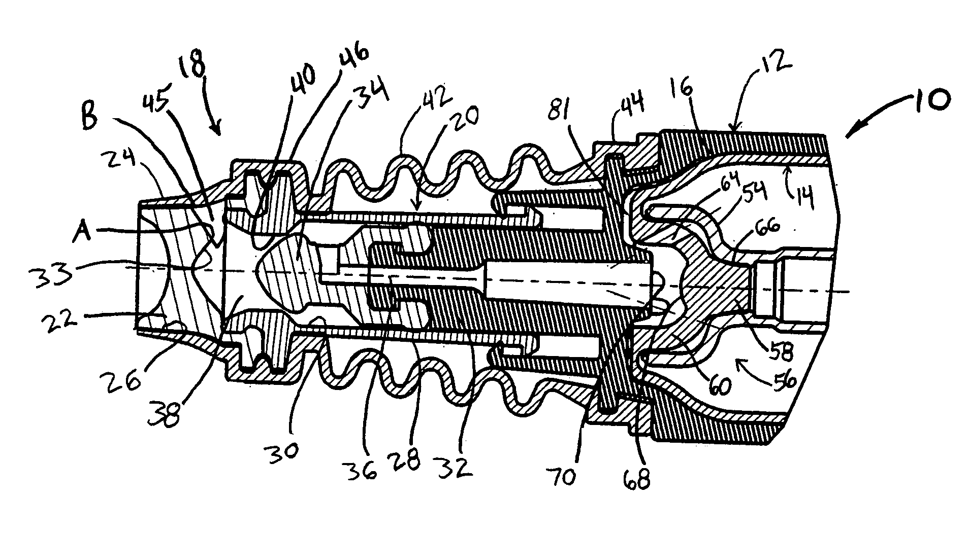
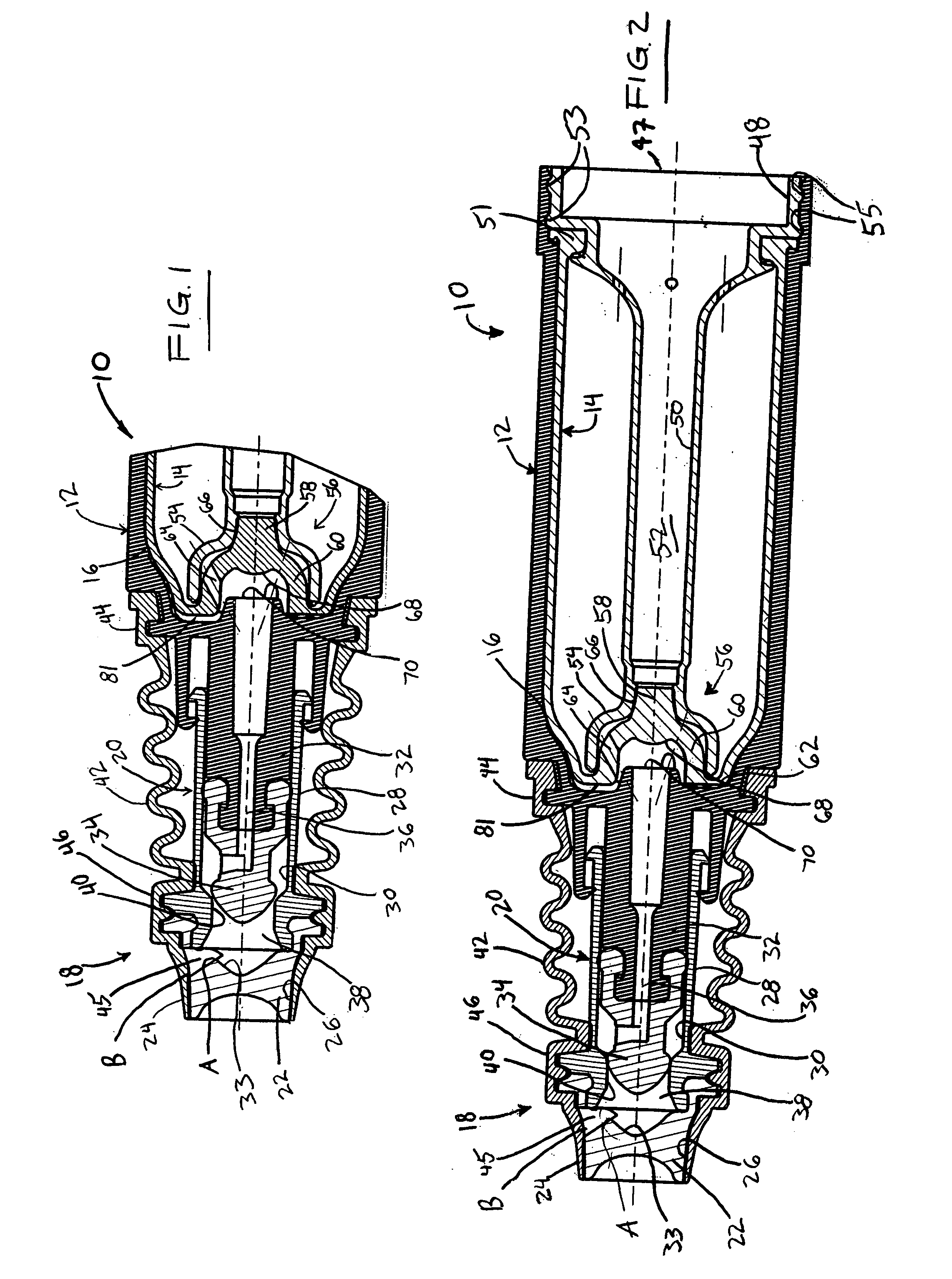
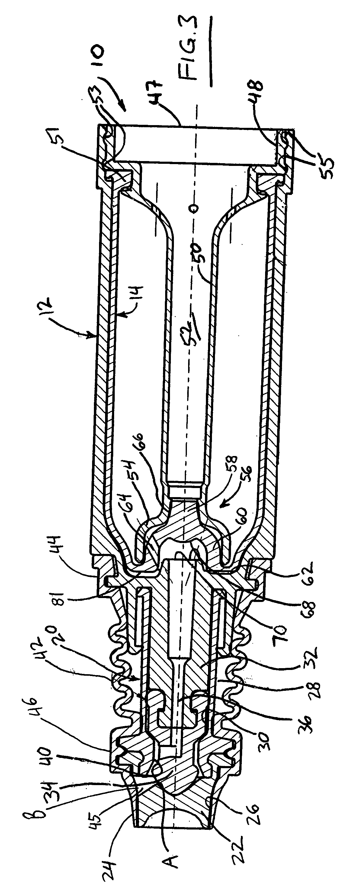
[0034] Referring to FIGS. 1-5, an exemplary embodiment of a delivery device or dispenser is indicated generally by the reference numeral 10. The delivery device 10 comprises a rigid vial or body 12, a flexible bladder 14 mounted within the rigid vial 12, and a storage chamber or reservoir 16 formed between the vial and bladder for receiving therein a fluid or other substance, such as a medicament. The delivery device 10 further comprises a dispensing nozzle 18 and a pump 20 coupled in fluid communication between the dispensing nozzle 18 and the storage chamber 16 for pumping metered doses of the fluid or other substance from the storage chamber 16 through the dispensing nozzle.

[0035] The dispensing nozzle 18 includes a relatively rigid valve seat 22 and a flexible, visco-elastic valve cover 24 mounted over the valve seat and defining an axially elongated, annular seam or interface 26 therebetween. As described further below, the pump 20 forces a metered dose of fluid or other subst...


PUM


Abstract

An ophthalmic delivery device includes a body defining a fluid reservoir and a pump in fluid communication with the reservoir. The delivery device also includes a nozzle that includes a dosage chamber for holding a dosage of fluid, a valve seat, and a valve cover. The valve cover extends about the valve seat and forms an interface therebetween and the valve seat includes an outlet aperture. The interface is in fluid communication with the outlet aperture and the dosage chamber, and at least part of the valve cover is movable between (i) a closed position with the valve cover engaging the valve seat to close the interface and form a fluid-tight seal therebetween, and (ii) an open position with at least part of the valve cover spaced away from the valve seat in response to fluid flowing through the outlet aperture at a pressure greater than a valve opening pressure to allow the passage of pressurized fluid therebetween. The valve seat and the valve cover are dimensioned to dispense the dosage of fluid through the interface at a velocity of equal to or less than 6 meters per second.

Description

CROSS-REFERENCE TO RELATED APPLICATION [0001] This patent application claims the benefit of U.S. Provisional Patent Application Ser. No. 60 / 519,961, filed Nov. 14, 2003, which is hereby expressly incorporated by reference as part of the present disclosure.FIELD OF THE INVENTION [0002] The present invention relates to delivery devices and methods of delivering fluids or other substances. BACKGROUND INFORMATION [0003] A typical prior art ophthalmic delivery device, such as an eye dropper, includes a vial for holding the fluid to be dispensed into the eye, and a cap and eye-dropper assembly. The cap includes a squeeze bulb for drawing fluid from the vial into a hollow tube of the dropper. The user must then hold the dropper over the eye, and squeeze the bulb to release a drop of fluid into an eye. One drawback associated with such prior art ophthalmic delivery devices is that many users have found them difficult to use. Some users have difficulty delivering drops into the eyes and inst...

Claims


Application Information

Patent Timeline
Patent Type & Authority Applications(United States)
IPC IPC(8): A61FA61F9/00A61M35/00
CPCA61F9/0008A61M11/007A61M35/003A61M2210/0612B05B11/0043B05B11/0048B05B11/0056B05B11/007B05B11/0072B05B11/3004B05B11/3056B05B11/307B05B11/3074B05B11/3077A61M15/08B05B11/026B05B11/028B05B11/1004B05B11/1056B05B11/107B05B11/1074B05B11/1077
Inventor PY, DANIELCHAN, JULIAN V.ATWOOD, JEFFREY M.
Owner MEDICAL INSTILL TECH
Learn More