RAID 6 disk array architectures

a technology of array controller and array controller, applied in the field of disk array controller, can solve the problems of requiring a complex array controller and computational time-consuming array controller to implement the reed, preventing the use of such codes in software, and high cos

Inactive Publication Date: 2005-07-28
PMC-SIERRA
View PDF21 Cites 54 Cited by
  • Summary
  • Abstract
  • Description
  • Claims
  • Application Information

AI Technical Summary

Problems solved by technology

RAID level 1, also called mirroring, provides simplicity and a high level of data availability, but at a relatively high cost due to the redundancy of the disks.
One drawback of the known RAID 6 implementation is that it requires a complex and computationally time-consuming array controller to implement the Reed-Solomon codes necessary to recover from a two-disk failure.
The complexity of Reed-Solomon codes may preclude the use of such codes in software, or may necessitate the use of expensive special purpose hardware.
Thus, implementation of Reed-Solomon codes in a disk array increases the cost, complexity, and processing time of the array.

Method used


Image

  • RAID 6 disk array architectures
  • RAID 6 disk array architectures
  • RAID 6 disk array architectures

Examples


Embodiment Construction

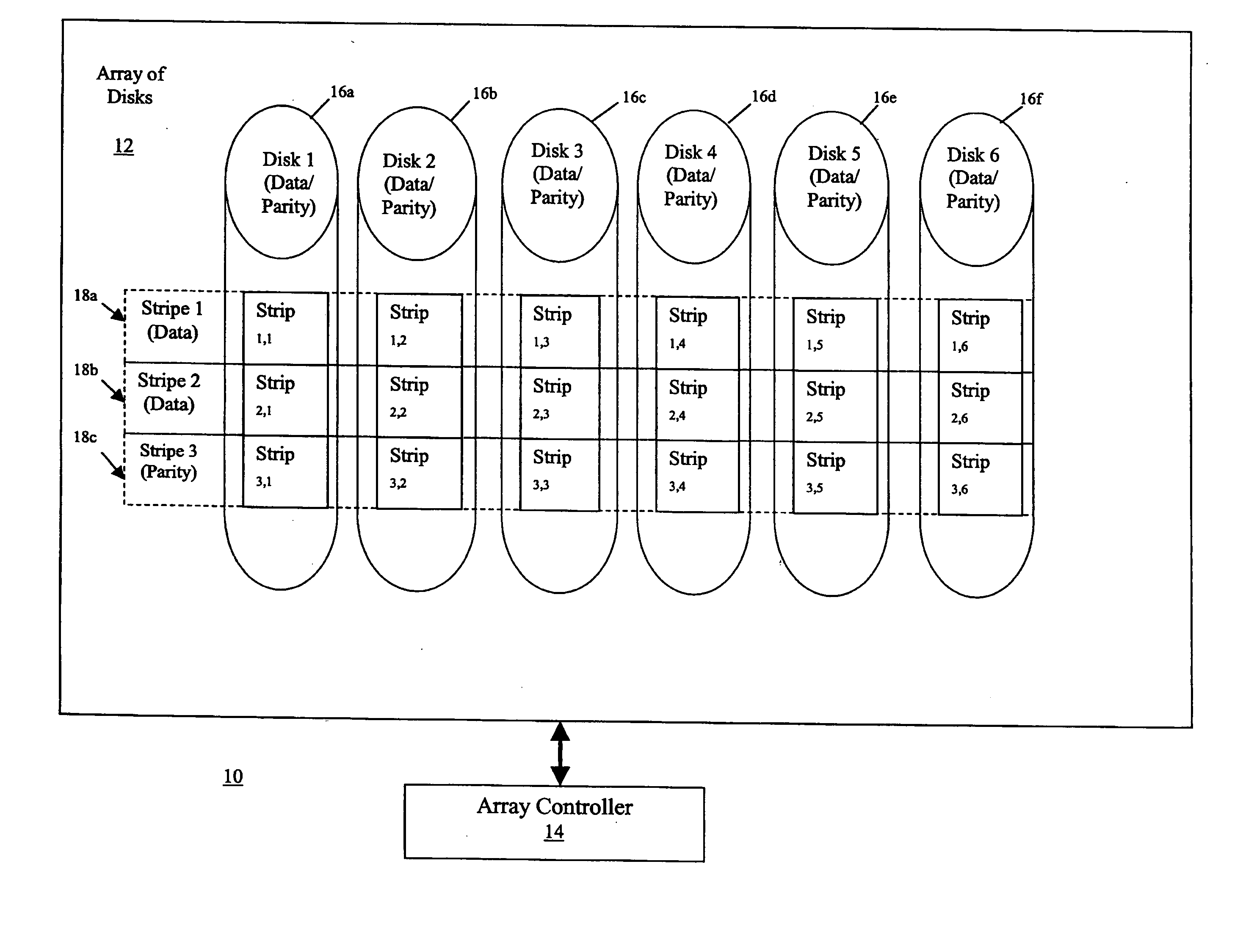
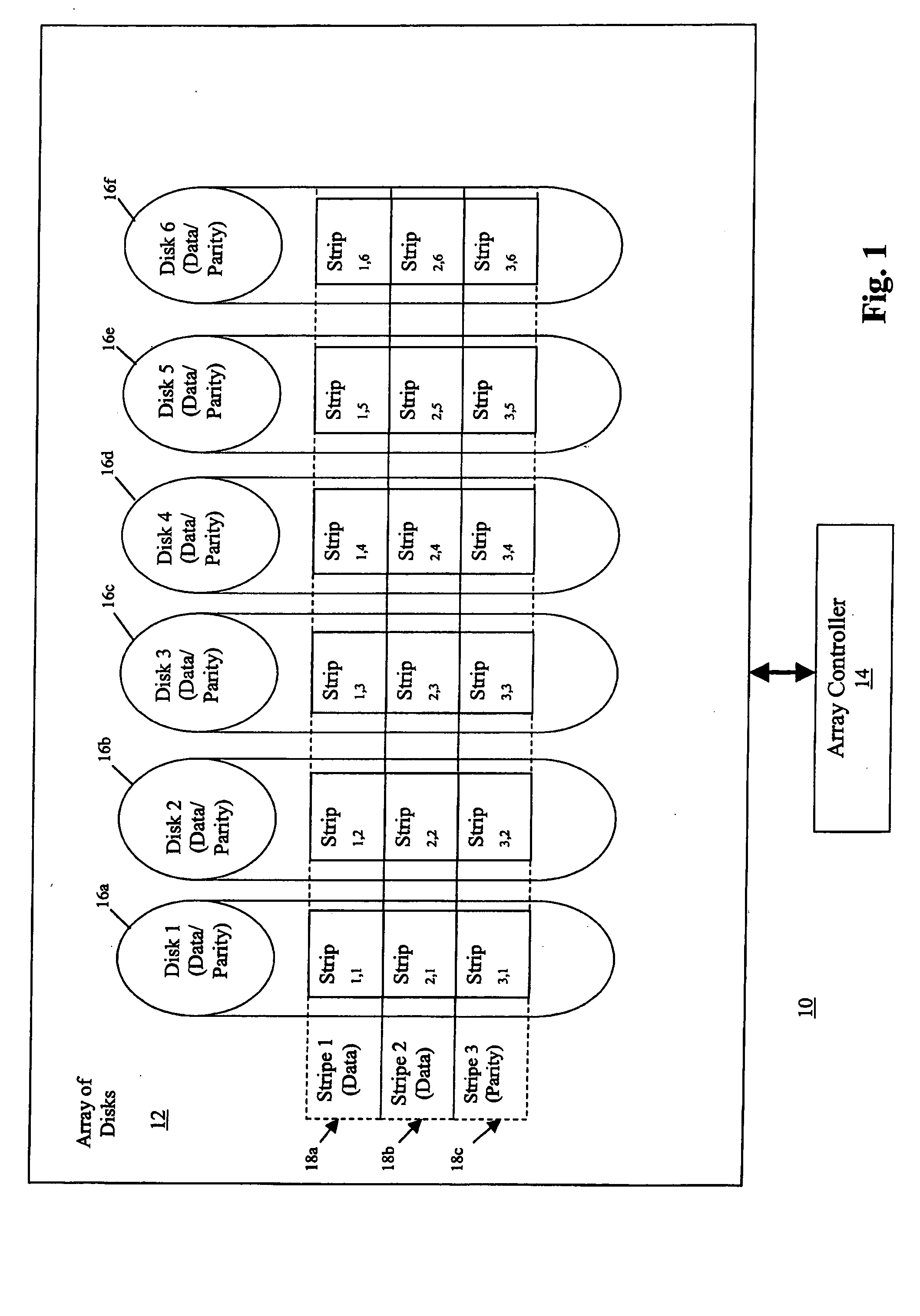
[0015]FIG. 1 illustrates a data storage system 10 including an array of disks 12 for storing data and an array controller 14 for controlling the storage and retrieval of data in the array 12. In one aspect of the invention, the system 10 may be configured as a RAID 6 type architecture, as understood by a skilled artisan. The array controller 14, coupled to the array of disks 12, allocates logical units, or strips, into logical rows, or stripes, extending across the physical disks in the array 12. Each disk in the array 12 may be consecutively indexed, each stripe in the array 12 may be consecutively indexed, and each strip may be indexed according to the corresponding disk and stripe membership. For example, the array 12 depicted in FIG. 1 includes six disks, disks 1-6 (16a-16f), allocated with three stripes, stripes 1-3 (18a-18c), so that each disk includes three strips indexed by both disk and stripe membership, and each stripe includes six strips allocated across the disks. Altho...


PUM


Abstract

A system and method for providing multiple disk fault tolerance in an N-column by R-row logical representation of stored elements in an array of N independent disks, R minus 1 being less than N divided by a number of disk failures F, includes assigning each strip containing data to at least F different parity groups so that each strip containing data in a respective column is assigned to parity groups different than other strips containing data in the column. The method also includes calculating, for each parity group, a parity value corresponding to all of the strips assigned to the parity group. The method further includes storing each of the parity values in strips of different columns, so that none of the strips containing data in a column are assigned to a parity group for which the parity value for the parity group is stored in the column.

Description

[0001] This application is a continuation-in-part of U.S. patent application Ser. No. 10 / 607,381 and it claims benefit of the Jun. 26, 2003 filing date thereof.BACKGROUND OF THE INVENTION [0002] 1. Field of the Invention [0003] The present invention is generally related to disk array architectures, and, specifically, to a RAID architecture, for providing two or more disk fault tolerance. [0004] 2. Related Art [0005] It is known how to store data in an array of disks managed by an array controller to control the storage and retrieval of data from the array is known. One example of such a system is a Redundant Array of Independent Disks (RAID) comprising a collection of multiple disks organized into a disk array managed by a common array controller. The array controller presents the array to the user as one or more virtual disks. Disk arrays are the framework to which RAID functionality is added in functional levels to produce cost-effective, high-performance disk systems having varyi...

Claims


Application Information

Patent Timeline
Patent Type & Authority Applications(United States)
IPC IPC(8): G06F11/00G06F11/10
CPCG06F2211/1057G06F11/1076
Inventor FREY, ALEXANDER HAMILTON JR.TREADWAY, TOMMY ROBERTNANDA, SANJEEB
Owner PMC-SIERRA
Why Eureka
Try Eureka