Visual communications system and method of controlling the same

a technology of communication system and communication method, applied in the field of visual communication system, can solve problems such as confusion of themes and inability to solve the above problems

Inactive Publication Date: 2005-07-28
CANON KK
View PDF26 Cites 193 Cited by
  • Summary
  • Abstract
  • Description
  • Claims
  • Application Information

AI Technical Summary

Benefits of technology

[0015] Therefore, according to the present invention, a plurality of users can pause the video playback at quite the same position. Even if the playback is paused near a scene boundary of the content, the plurality of users can view the same image. Thereby, the users can enjoy a conversation about quite the same image while viewing that image.

Problems solved by technology

The arrangement, however, does not resolve the above problem.
In this situation, the images displayed on their screens will be quite different from each other, which may cause theme confusion in their conversation about the program or the paused scene.
This may cause a situation where they are talking about different parts of the content while viewing the same content.

Method used


Image

  • Visual communications system and method of controlling the same
  • Visual communications system and method of controlling the same
  • Visual communications system and method of controlling the same

Examples


first embodiment

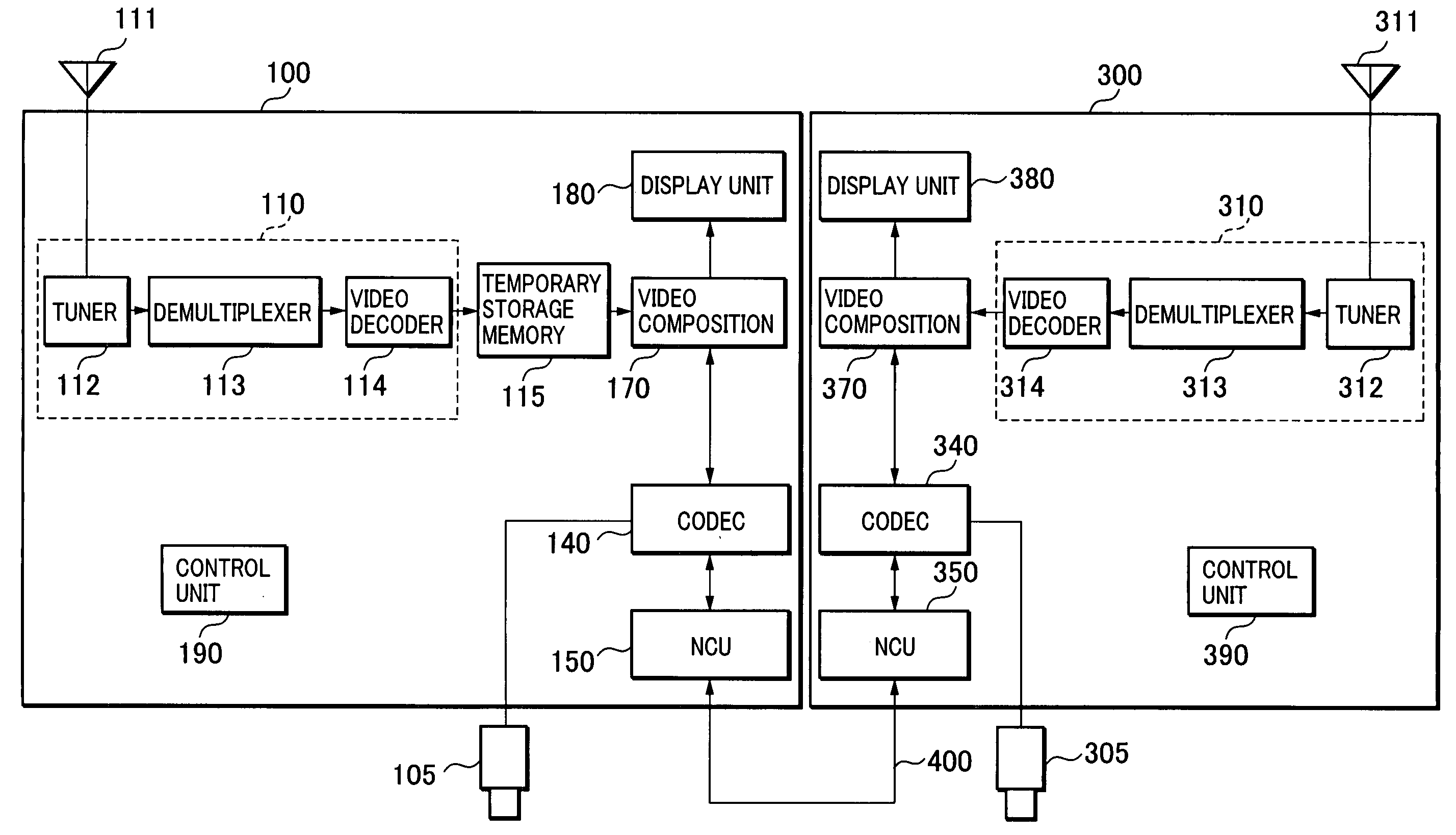
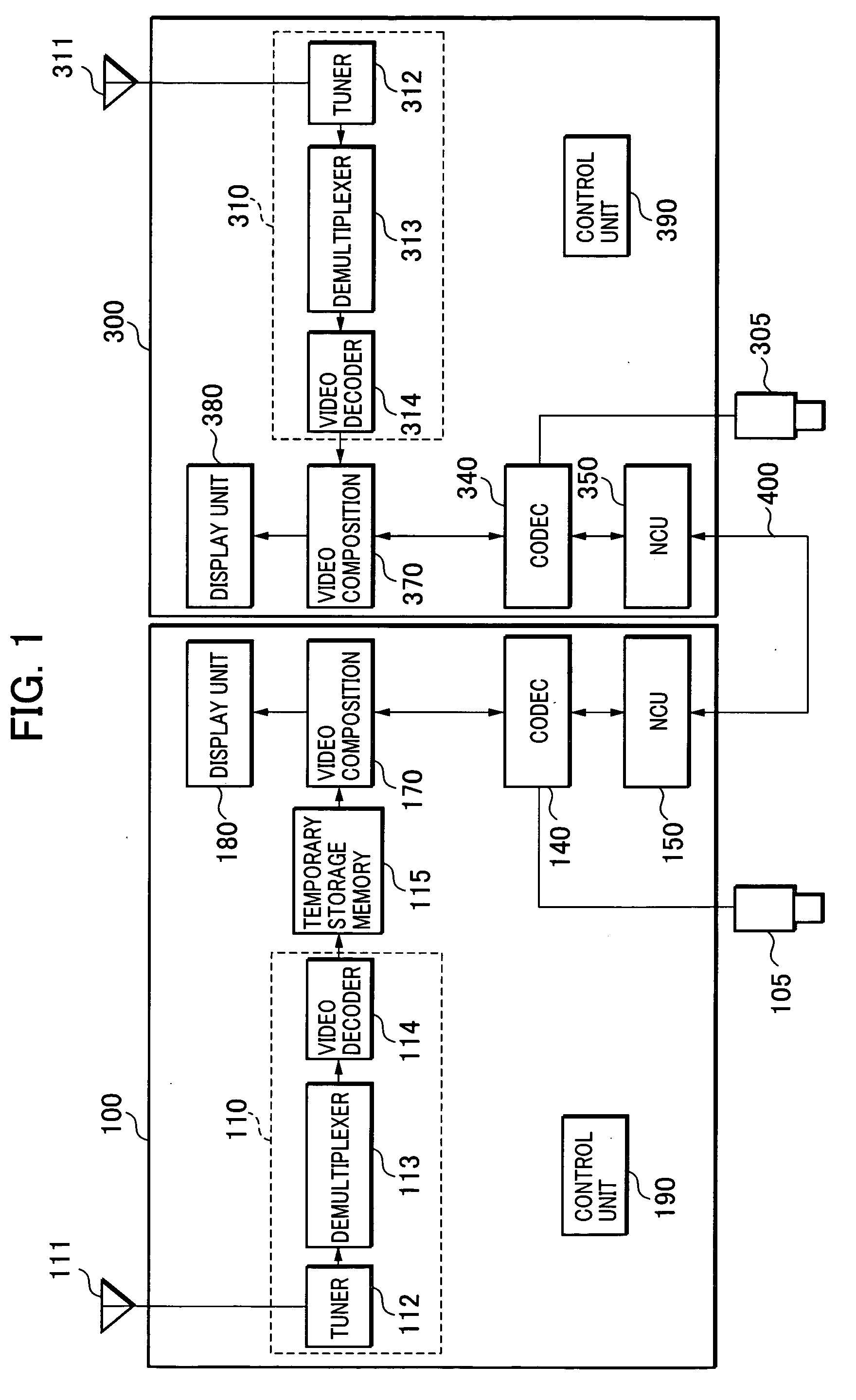
[0030] Referring to FIG. 1, there is shown an outline block diagram of a first embodiment of the present invention. A user A uses a video communications terminal 100 as communications terminal equipment and a user B uses a video communications terminal 300. Television cameras 105 and 305 are for use in shooting video of the users A and B, respectively. Although the video communications terminal 100 and the video communications terminal 300 have the same configuration and functions, the video communications terminal 100 is assumed here to initiate the operation. The configuration and functions of the video communications terminals 100 and 300 will be described below.

[0031] A broadcast program receiving unit 110 has the same configuration as a general digital television. A tuner 112 receives a signal from an antenna 111, demodulates the received data and corrects any error, and outputs transport stream (TS) data. A demultiplexer 113 separates desired video data, audio data, and subti...

second embodiment

[0055] A second embodiment of the present invention will be described hereinafter. FIG. 5 shows an outline block diagram of the second embodiment. The same reference numerals have been retained for the same parts as those shown in FIG. 1.

[0056] A video communications terminal 100a has a function of controlling a video cassette recorder (VCR) 120 as a video playback unit to capture the played back video, in addition to the functions of the video communications terminal 100a. The VCR 120 plays back the content recorded on the cassette tape. A control unit 190a of the video communications terminal 100a can control the playback, stop, pause and other operations of the VCR 120. The video communications terminal 100a and the VCR 120 are connected via, for example, an IEEE 1394 serial bus standardized as the IEEE 1394-1995 standard by the Institute of Electrical and Electronics Engineers, Inc., the video and audio data are transferred as isochronous data, and a control command of the VCR ...

third embodiment

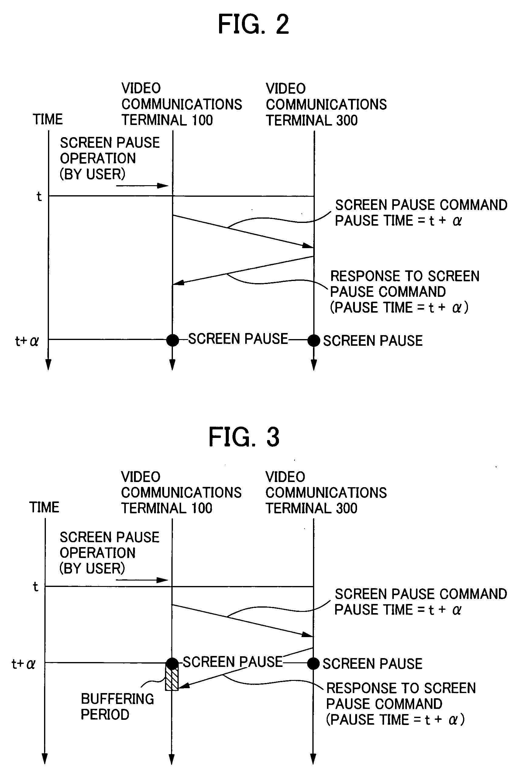
[0075]FIG. 9 illustrates the operation of a third embodiment of the present invention which involves a change in operation from the first embodiment. Therefore, the following describes only the changes with reference to FIG. 9.

[0076] It is assumed that the user A performed a screen pause operation at time t. At that time, the control unit 190 controls the video composition unit 170 to pause the screen and transmits the screen pause command to the video communications terminal 300 via the CODEC 140 and the NCU 150. Then, the video communications terminal 100 awaits a response from the video communications terminal 300 and starts the temporary storage of the video data from the video decoder 114.

[0077] Upon receiving the screen pause command via the NCU 350 and the CODEC 340, the control unit 390 of the video communications terminal 300 controls the video composition unit 370 to pause the screen and identifies the current time of t+α. The video communications terminal 300 transmits ...


PUM


Abstract

A visual communications system and a method of controlling the same for pausing the screens of two terminals at quite the same image. Video communications terminals receive the same channel in their respective broadcast program receiving units. A first video communications terminal temporarily stores the video of the received channel in the temporary storage memory. When a user pauses operation of the first terminal, it temporarily stores a screen pause time obtained by adding a predetermined time to the current time, and transmits a screen pause command and the screen pause time to a second video communications terminal. The second terminal pauses the video at the screen pause time if possible in time. Otherwise, it pauses the video immediately, and transmits a response with its own image pause time to the first terminal. The first terminal displays an image corresponding to the image pause time of the second terminal memory.

Description

BACKGROUND OF THE INVENTION [0001] 1. Field of the Invention [0002] The present invention relates to a visual communications system comprising communications terminals connected via a network and a method of controlling the same. [0003] 2. Description of the Related Art [0004] There has been suggested an interactive-network, simultaneous-viewing system enabling a user to view the same TV program or the same video content as another party by using a TV phone or the like, while enjoying a conversation about the movie or the program they are viewing. [0005] In this regard, transferring a control command requires a certain amount of time and therefore, if one party pauses the content while viewing the same content as the other party by using the TV phone or the like, both parties cannot pause the content at quite the same position. [0006] Japanese Laid-Open Patent Publication (Kokai) No. H7-245594 (1995-245594), corresponding to U.S. Pat. No. 5,684,526, discloses an arrangement in which...

Claims


Application Information

Patent Timeline
Patent Type & Authority Applications(United States)
IPC IPC(8): H04N5/44H04N5/76H04N5/765H04N5/93H04N7/14
CPCH04N5/76H04N7/147H04N21/4788H04N21/4325H04N21/4223
Inventor MATSUMOTO, YUICHIYAMAMOTO, TAKASHIKUTSUNA, MASAKIMORI, SHIGEKI
Owner CANON KK
Why Eureka
Try Eureka