Retaining device

a technology of retaining device and sleeve, which is applied in the direction of flexible cover, container, domestic articles, etc., can solve the problems of not being able to compress on itself, being only radially extensible, and not being able to adapt vertically

Inactive Publication Date: 2005-08-04
LOREAL SA
View PDF6 Cites 9 Cited by
  • Summary
  • Abstract
  • Description
  • Claims
  • Application Information

AI Technical Summary

Benefits of technology

[0010] According to one feature, an arrangement is provided which is capable of surrounding and protecting an item to be retained, in a manner such that the arrangement is also capable of assuming minimum dimensions when not in use, and which is simple to mount around the item. According to a preferred example of the invention, the arrangement is variable in shape and can present an outer envelope surface having a non-circular cross-section and / or a shape different from that of the object to be retained. Similarly, the internal space formed to accommodate the object is not necessarily cylindrical or circular in cross-section and can adapt to objects having a complex shape.
[0016] Advantageously, the connecting arrangement can be deformed so as to form a sleeve capable of surrounding the object over its full height relative to the support, and in particular relative to the axis X. This advantageous arrangement provides the ability to surround objects of different heights relative to the axis X. The arrangement is particularly advantageous for objects that have substantially the same cross-section relative to a plane orthogonal to the axis X and where the cross-sections are preferably substantially constant along the axis X.
[0022] According to an example of one embodiment of the connecting arrangement, the projected internal cross-section of the aperture(s) in the connecting arrangement varies in relation to its position, between its position at rest and its position when deformed. In particular, when the connecting arrangement is deformed, the projected internal cross-section of the aperture(s) is smaller than the internal cross-section of the apertures in the non-deformed connecting means. The greater the deformation of the connecting arrangement, the more the projected internal cross-section of the aperture is reduced.
[0025] In accordance with an alternative or optional feature, the plate can include a closure element capable of cooperating with an upper face of the plate, and particularly with an end of the object placed in the retaining device, with this end projecting beyond the level of the opening in the upper plate. Because the closure element is mounted integrally on the plate, the object can keep the connecting arrangement deformed by holding the support away from the closure element and therefore away from the plate.

Problems solved by technology

However, in the case where the objects can have different heights, the sleeve might not be adaptable to cover the object or objects over their full height.
In effect, the sleeve thus formed is only radially extensible and is not vertically adaptable.
In addition, with the above arrangement, because the cellular structure is designed to present properties of radial extension such that each cell has at least two walls oriented parallel to an axis of insertion of the object into the sleeve, such a structure is not capable of compressing on itself so as to present a minimum vertical size when not in use.
Moreover, this minimum height cannot be achieved at rest, and is obtained only when maximum radial constraint is applied thereto.
Another problem with these sleeves is that they require complex manipulation and cannot be readily handled by packaging machines.
This bag poses a problem in that it fails to protect the objects it contains against external impacts, particularly when the impacts are exerted radially in relation to the outer surface of the side walls.
This bag poses another problem in that the outer envelope surface which it defines is necessarily cylindrical and circular in cross-section.
It is therefore not possible to readily secure such a bag in a parallelepiped package of larger size.
Similarly, an object placed inside such a bag will not be retained and is likely to remain loose if it has a shape other than cylindrical and circular in cross-section.

Method used


Image

  • Retaining device
  • Retaining device
  • Retaining device

Examples


Embodiment Construction

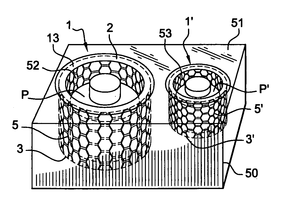
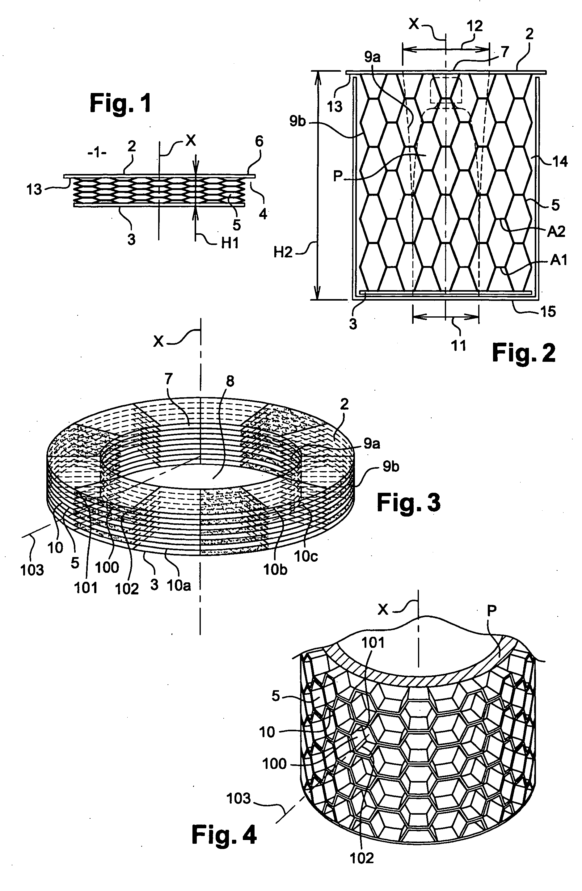
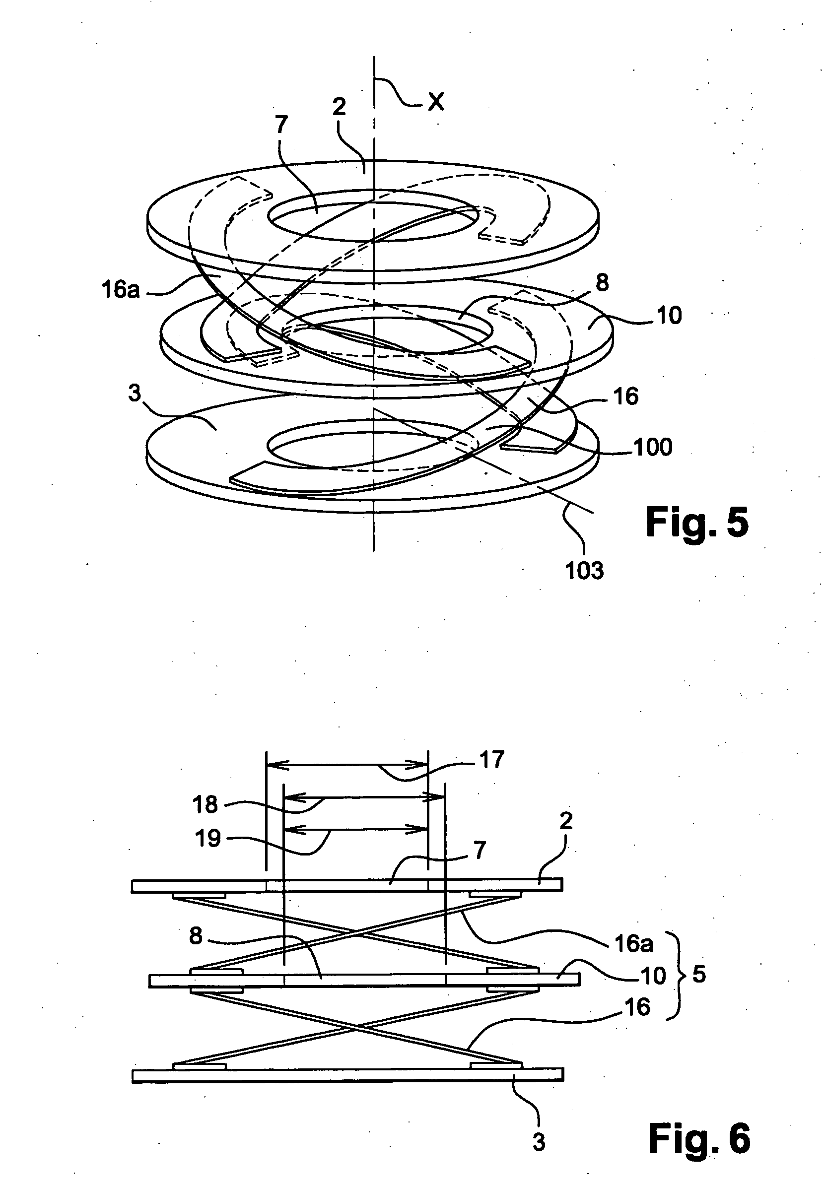
[0047]FIG. 1 illustrates a retaining device 1 according to the invention. The device 1 includes a plate 2 and a support 3. The support 3 is attached to a lower face 4 of the plate 2 by a connecting arrangement 5. The connecting arrangement 5 can be deformed so that the plate 2 moves away from the support 3 in a movement parallel to an axis X.

[0048] According to the example of this embodiment, the plate 2 is defined in a plane such that the lower face 4 and the upper face 6 of this plate 2 are parallel to this plane. Preferably, the plane of the plate 2 is defined orthogonally to the axis X.

[0049] By way of example, the plate 2 can be obtained by cutting from cardboard having a thickness, for example, on the order of 1 to several millimeters. The outline imparted to this plate 2 can be square, rectangular, circular, ovoid, or any other geometrical shape. Generally, the shape imparted to this outline is dependent on the end use of the retaining device. In effect, the plate 2 is gene...


PUM


Abstract

A retaining device for an object including a plate incorporating an aperture allowing the insertion and withdrawal of the object. A lower face of the plate is attached to a support by a connecting arrangement, and a separation movement between the plate and the support causes deformation of the connecting arrangement so as to form a sleeve around the object. Walls of the connecting arrangement are preferably defined radially relative to the object and facilitate its protection. The device can be advantageously mounted inside a case capable of accommodating the object.

Description

CROSS REFERENCE TO RELATED APPLICATIONS [0001] This document claims priority to French Application Number 03 50782, filed Nov. 4, 2003 and U.S. Provisional Application No. 60 / 519,651, filed Nov. 14, 2003, the entire contents of which are hereby incorporated by reference.BACKGROUND OF THE INVENTION [0002] 1.Field of the Invention [0003] The invention relates to a retaining device that can, for example, be used to secure an object in a case. By way of example, the device can be used in the field of dispensing and / or packaging devices disposed in cardboard cases of generally parallelepiped shape. The objects packaged therein can have a different envelope outline or profile, e.g., smaller than that of the parallelepiped formed by the cardboard case. [0004] 2. Discussion of Background [0005] FR-A-2,571,028 describes a sleeve fashioned from a cellular structure capable of being mounted about an object to be protected or concealed. This sleeve has a structure similar to that provided for a...

Claims


Application Information

Patent Timeline
Patent Type & Authority Applications(United States)
IPC IPC(8): B65D81/05
CPCB65D81/05B65D65/44
Inventor WINCKELS, MATHILDE
Owner LOREAL SA
Why Eureka
Try Eureka