Fence post

Inactive Publication Date: 2005-08-04
DEUPREE ALAN
View PDF11 Cites 20 Cited by
  • Summary
  • Abstract
  • Description
  • Claims
  • Application Information

AI Technical Summary

Benefits of technology

[0003] Over the centuries fence posts have been manufactured from a wide variety of materials including unprocessed sticks and tree limbs, various wooden configurations manufactured by conventional wood processing techniques, metal tubes formed from iron, steel, and other

Problems solved by technology

One difficulty that has heretofore been common to all fence post designs comprises the fact that a fastener of some type is necessary in order to secure each fence wire to each fence post.
As will therefore be understood, the construction of a fence utilizing conventional fence post designs entail

Method used


Image

  • Fence post
  • Fence post
  • Fence post

Examples


first embodiment

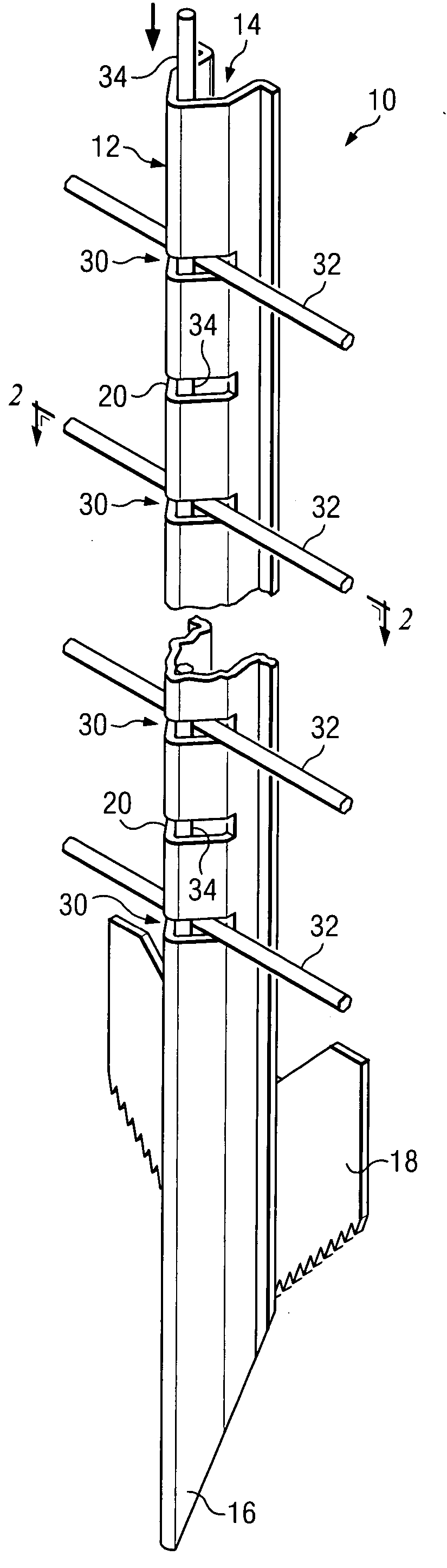
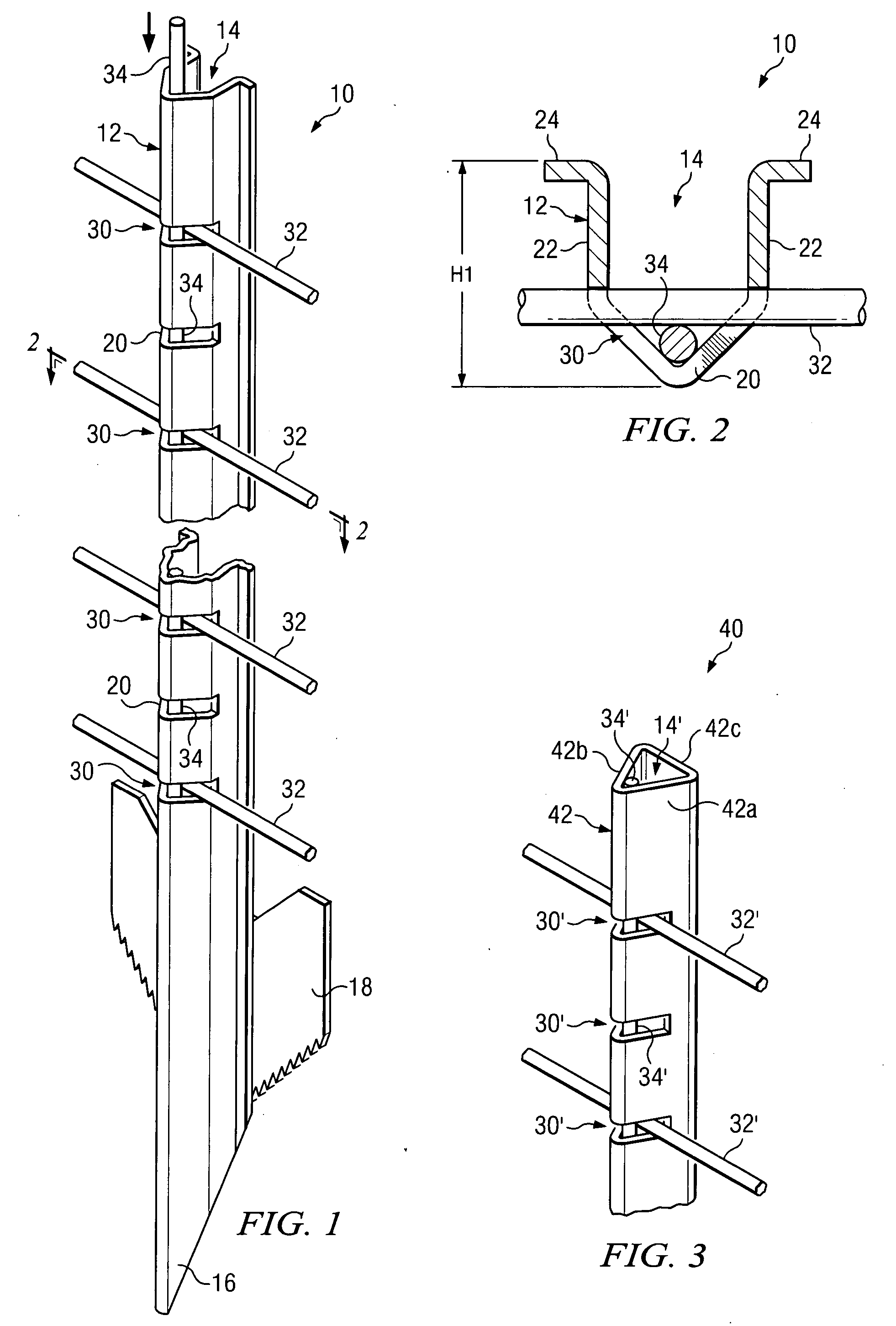
[0021] Referring now to the Drawings, and particularly to FIGS. 1 and 2 thereof, there is shown a fence post 10 comprising the invention. The fence post 10 comprises a wall 12 defining an interior 14. The wall 12 of the fence post 10 comprises a unitary construction formed from steel or any other high strength, weather resistance material, however, multiple component walls may also be used in the practice of the invention. The interior 14 defined by the wall 12 may be either open as shown in FIGS. 1 and 2, or partially closed, or fully closed depending upon the requirements of particular applications of the invention.

[0022] Referring specifically to FIG. 1, the lower end of the fence post 10 comprises a beveled point 16. The beveled point 16 facilitates insertion of the fence post 10 into the ground. As will be appreciated by those skilled in the art, other types and kinds of lower end configurations for the fence post 10 may be utilized in the practice of the invention dependent up...

second embodiment

[0029] Referring to FIG. 3 there is shown a fence post 40 comprising the invention. Many of the component parts of the fence post 40 are substantially identical in construction and function to component parts of the fence post 10 illustrated in FIGS. 1 and 2 and described hereinabove in conjunction therewith. Such identical component parts are designated in FIG. 3 with the same reference numerals utilized above in the description of the fence post 10, but are differentiated therefrom by means of a prime (′) designation.

[0030] The fence post 40 comprises a triangularly shaped wall 42. The wall 42 comprises three interconnected panels 42a, 42b and 42c. As will be appreciated by those skilled in the art, when the wall 42c is utilized the interior 14′ of the fence post 40 is completely enclosed. However, the wall 42c may be dispensed with entirely in which case the interior 14′ of the fence post 40 is open. The wall 42c can also comprise inwardly turned flanges in which case the interio...

third embodiment

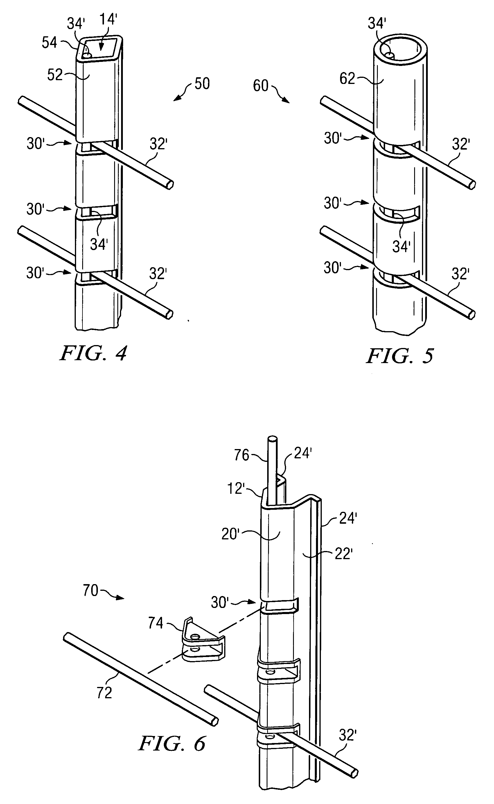
[0031] Referring to FIG. 4 there is shown a fence post 50 comprising the invention. The fence post 50 includes numerous component parts which are substantially identical in construction and function to component parts of the fence post 10 illustrated in FIGS. 1 and 2 and described hereinabove in conjunction therewith. Such identical component parts are designated in FIG. 4 with the same reference numerals utilized in the description of the fence post 10 but are differentiated therefrom by means of a prime (′) designation.

[0032] The fence post 50 differs from the fence post 10 of FIGS. 1 and 2 in that the fence post 50 comprises a wall 52 which is square or rectangular in configuration. The horizontally disposed slots 30′ extend into the wall 52 through one corner 54 thereof thereby extending into the interior 14′ of the fence post 50.


PUM


Abstract

A nominally vertically disposed fence post comprises a wall defining an interior. A plurality of nominally horizontally disposed slots are located at equally spaced intervals along the length of the fence post and extend through the wall into the interior thereof. Selected slots receive fence wires therein. A keeper rod extends through the interior of the fence post between the wall and the fence wires to retain the fence wires in the slots. Electrified fence wires are each received in an insulated insert which is received in one of the slots and are retained therein by an insulated keeper rod.

Description

CLAIM OF PRIORITY [0001] This application claims priority of prior provisional Application Ser. No. 60 / 541,882 filed Feb. 4, 2004.TECHNICAL FIELD [0002] This invention relates generally to fence posts, and more particularly to an improved fence post design which is both easier to use and more pleasing in appearance as compared with traditional fence posts. BACKGROUND AND SUMMARY OF THE INVENTION [0003] Over the centuries fence posts have been manufactured from a wide variety of materials including unprocessed sticks and tree limbs, various wooden configurations manufactured by conventional wood processing techniques, metal tubes formed from iron, steel, and other metals, etc. A fence post design that is currently in wide spread use is formed from steel and is T-shaped in horizontal cross section. Protrusions are provided at equally spaced intervals along the length of the fence post to facilitate alignment of fence wires therewith. [0004] One difficulty that has heretofore been comm...

Claims


Application Information

Patent Timeline
IPC IPC(8): E04H12/22E04H17/12E04H17/20
CPCE04H12/2215E04H17/20E04H17/12
Inventor DEUPREE, ALAN
Owner DEUPREE ALAN
Why Eureka
Try Eureka