Lens molding die assembling device, lens molding die washing method, and lens molding die assembling method

Inactive Publication Date: 2005-08-04
SEIKO EPSON CORP
View PDF3 Cites 9 Cited by
  • Summary
  • Abstract
  • Description
  • Claims
  • Application Information

AI Technical Summary

Benefits of technology

[0003] The present invention has been made in view of the above circumstances, and it has for its first object to provide a lens-casting-mold assembling apparatus which can effic

Problems solved by technology

Therefore, in a case where the adhesive tape is directly drawn out from the adhesive tape roll and then stuck, it exten

Method used


Image

  • Lens molding die assembling device, lens molding die washing method, and lens molding die assembling method
  • Lens molding die assembling device, lens molding die washing method, and lens molding die assembling method
  • Lens molding die assembling device, lens molding die washing method, and lens molding die assembling method

Examples


Example

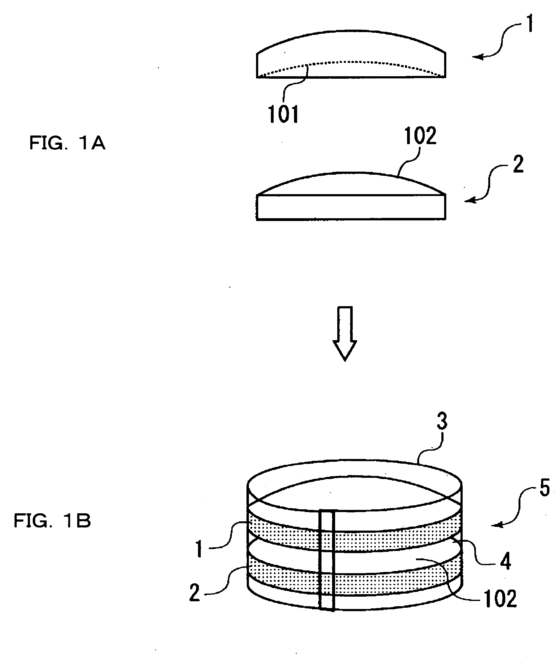
[0017] Now, embodiments of a lens-casting-mold assembling apparatus, a lens-casting-mold cleaning method and a lens-casting -mold assembling method according to the present invention will be described, but the present invention shall not be restricted to the embodiments described below. FIG. 1 is a schematic view showing a concave mold and a convex mold which constitute a lens-casting-mold assembly. The lens-casting-mold assembling apparatus of the present invention employs a concave mold 1 having a surface 101 for forming the convex surface of a lens, and a convex mold 2 having a surface 102 for forming the concave surface of the lens, in a pair as shown in FIG. 1(a). It is an apparatus in which, as shown in FIG. 1(b), a lens-casting-mold assembly 5 is assembled in such a way that the convex-surface forming surface 101 and concave-surface forming surface 102 of the respective lens-Casting-molds 1, 2 are arranged in opposition with a predetermined distance spaced therebetween, and t...


PUM

PropertyMeasurementUnit
Distanceaaaaaaaaaa
Contentaaaaaaaaaa
Volatilityaaaaaaaaaa

Abstract

An apparatus is constructed by accommodating in one dust-proof room 11, a concave-mold first cleaning device 21 which abrades the convex-surface forming surface 101 of a concave mold 1, a concave-mold second cleaning device 22, a concave-mold drying device 23, a convex-mold first cleaning device 24 which abrades a concave-surface forming surface for a lens, a convex-mold second cleaning device 25, a convex-mold drying device 26, an inversion device 30 which inverts the concave mold 1 or a convex mold 2 up or down, a positioning device 50 which brings the geometric centers of the concave mold 1 and the convex mold 2 into coincidence and then arranges them in opposition, and a tape winding device 60 which winds an adhesive tape onto the peripheral surfaces of the concave mold 1 and convex mold 2 so as to seal the gap between these molds, thereby to provide the lens-casting-mold assembling apparatus which can efficiently assemble a lens-casting-mold assembly, and which saves space.

Description

TECHNICAL FIELD [0001] The present invention relates to a lens-casting-mold assembling apparatus which assembles a lens-casting-mold assembly for manufacturing an eyeglass lens by injection and curing in a state where an adhesive tape is wound onto the peripheral surfaces of a convex mold and a concave mold, a lens cleaning method which cleans the forming surfaces of the convex mold and the concave mold, and a lens-casting-mold assembling method which assembles the cleaned convex and concave molds. TECHNICAL BACKGROUND [0002] Heretofore, as a method for manufacturing a plastic lens, there has been known tape molding wherein, as shown in FIG. 1, a lens-casting-mold assembly 5 is assembled in such a way that two opposing molds, a concave mold 1 for forming a convex surface and a convex mold 2 for forming a concave surface, are arranged in opposition, and that an adhesive tape 3 is applied onto the peripheral surfaces of these molds, thereby to seal the gap between these molds. As indi...

Claims


Application Information

Patent Timeline
IPC IPC(8): G02C7/02B29C33/30B29C33/72B29C39/02B29C39/22B29C39/26B29L11/00
CPCB29C33/72B29L2011/0016B29C39/22B29C39/02B29C39/26B29D11/00
Inventor SANO, YOSHIO
Owner SEIKO EPSON CORP
Why Eureka
Try Eureka