Serial-connection fitting assembly and punch appratus applied therefore

Inactive Publication Date: 2011-03-10
TSAI LORE
View PDF2 Cites 0 Cited by
  • Summary
  • Abstract
  • Description
  • Claims
  • Application Information

AI Technical Summary

Benefits of technology

[0010]The joining member adjacent to the in-position fitting member is broken as the punch body punches the frontmost fitting member that is in position; thereby the punched fitting member could be speedy outwardly for inserting into the pre-hole of the plates. Thus, the requirements to increase the insertion efficiency of the fitting members and the assembly efficiency of the plates would be achieved.
[0011]Furthermore, the punch apparatus provides continuous p

Problems solved by technology

Nevertheless, the connection strength thereby isn't strong enough for use.
However, the fabrication process is still time-wasting and inconvenie

Method used


Image

  • Serial-connection fitting assembly and punch appratus applied therefore
  • Serial-connection fitting assembly and punch appratus applied therefore
  • Serial-connection fitting assembly and punch appratus applied therefore

Examples


Example

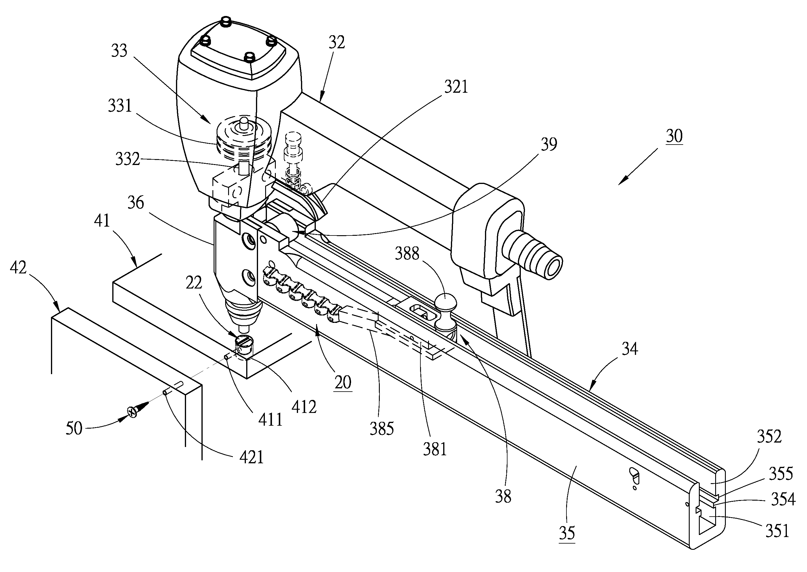
[0025]Certain embodiments as disclosed herein provide for a serial-connection fitting assembly which has a plurality of fitting members and joining members staggered in alignment. The serial-connection fitting assembly can be loaded into a punch apparatus for speedy insertion to the respective plates, so as to shorten time and labor consumption and to meet mass manufacture during the fabrication of plates' connection.

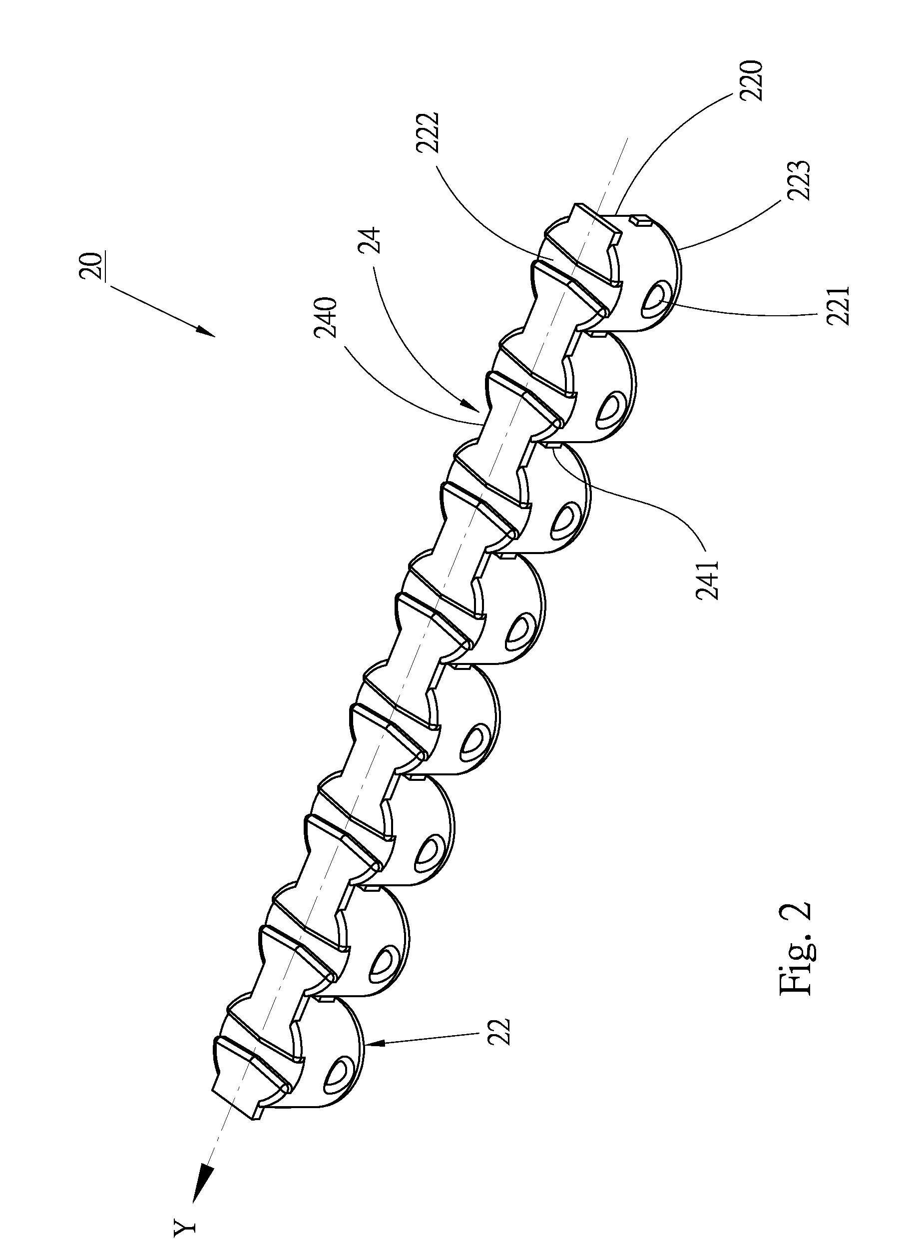
[0026]FIGS. 2 and 3 illustrate a preferred embodiment of a serial-connection fitting assembly 20 according to the present invention. The serial-connection fitting assembly 20 includes a plurality of fitting members 22 and a plurality of joining members 24. The joining members 24 are staggered with the fitting members 22; each joining member has two lateral sides connected to adjacent two fitting members. Therefore, the fitting members 22 can be set in alignment through the connection between the joining members 24. The joining members 24 and the fitting members 22 can b...


PUM


Abstract

A serial-connection fitting assembly and a punch apparatus applied therefore are disclosed. The serial-connection fitting assembly includes a plurality of fitting members and a plurality of joining members staggered with the fitting members in alignment. Each fitting member has a conjunction hole radially arranged therein, and a groove indented radially on a top surface thereof with the same axial direction of the conjunction hole. The serial-connection fitting assembly is loaded in the punch apparatus, and the fitting members could be punched into pre-holes of respective plates one by one. Therefore, the labor hour for inserting the fitting members could be saved, and the efficiency for assembling the plates would be increased.

Description

BACKGROUND[0001]1. Field of the Invention[0002]The present invention relates generally to a member could be punched and an apparatus for utilizing said member, and is more specifically concerned with a serial-connection fitting assembly and a punch apparatus applied therefore.[0003]2. Background of the Invention[0004]Conventional desks, tables or furniture the like are made by plates, which are connected to one another by nails, screws or bolts. Nevertheless, the connection strength thereby isn't strong enough for use.[0005]Another conventional fabrication of plates' connection is illustrated in FIG. 1. A first plate 12 is pre-formed with a through hole 122 and an indentation 124 communicated with the through hole 122. A second plate 14 is pre-formed with a through hole 142. A fitting member 10 is inserted into the indentation 124 of the first plate 12 in a manual way. The through holes 122, 142 are aligned with each other in order to insert a fastener 16, such as screws, for puttin...

Claims


Application Information

Patent Timeline
IPC IPC(8): B23P19/00F16B17/00B23Q7/10
CPCF16B27/00Y10T403/70Y10T29/535F16B37/005
Inventor TSAI, LORE
Owner TSAI LORE
Why Eureka
Try Eureka