Methods for manufacturing decorative laminate panels

Active Publication Date: 2021-05-27
AGFA NV
View PDF1 Cites 2 Cited by
  • Summary
  • Abstract
  • Description
  • Claims
  • Application Information

AI Technical Summary

Benefits of technology

The patent text describes a way to efficiently assemble decorative laminate panels so that they can be placed on a floor to create a personalized or customized image. This is done by using a positioning code on the back-side of the panels. The technical effect of this is the ability to have well-made and accurately placed floor panels that reflect the unique design of a person or place.

Problems solved by technology

Gravure printing requires a laborious set-up before actual printing can start.
Hence, large production batches are made that result in a considerable stock of decorative laminate panels.
There has been some limited manufacturing, where company names and logos were printed on individual decorative laminate panels.
However so far, it has proven to be impossible to manufacture in an economical manner flooring panels having a personalized image covering multiple flooring panels.
This means that the cutting of decorative laminate panels (see FIG. 1 B) has to be adapted, which results in cutting errors and a distorted printed image once mounted as a floor.
In addition, the true capabilities of inkjet printing are not yet exploited as it is not possible for a customer to order, in a cost-efficient manner, a personalized flooring laminate due to the complexity of the manufacturing process for decorative panels.
The fact is that small personalized orders can easily get lost in the mass product manufacturing and that it is not easy to have a fast, error free delivery of the order to the customer.

Method used


Image

  • Methods for manufacturing decorative laminate panels
  • Methods for manufacturing decorative laminate panels
  • Methods for manufacturing decorative laminate panels

Examples


Embodiment Construction

Manufacturing Methods

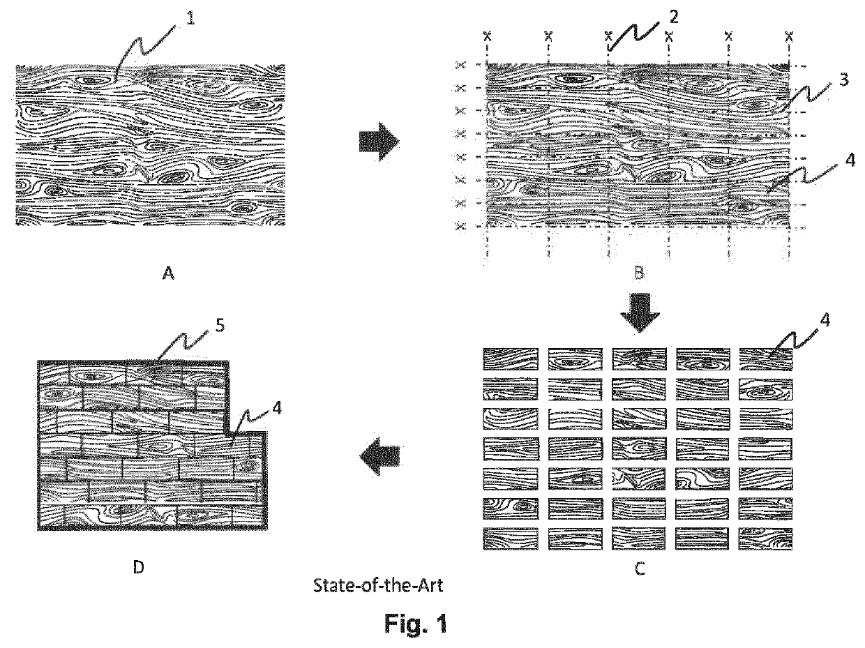
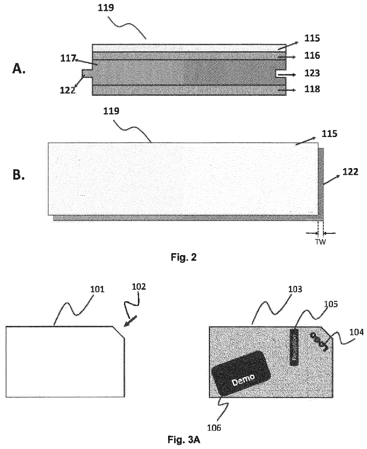
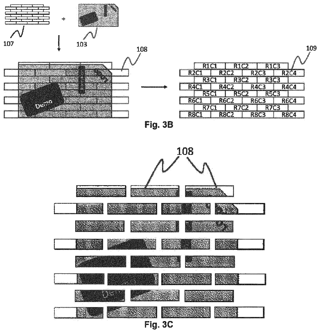
[0024]A method for manufacturing a personalized or customized decorative surface (103) having decorative laminate panels (119) according to a preferred embodiment of the present invention including the steps of: segmenting a digital image of the personalized or customized decorative surface (103) into a plurality of decorative laminate panel images (108), wherein each decorative laminate panel image (108) is sized to fit on a decorative laminate panel (119); assigning a positioning code (109) to a decorative laminate panel image (108) for identifying its position in the digital image of the personalized or customized decorative surface (103); creating a non-staggered digital layout (110) of the plurality of decorative laminate panel images (108); inkjet printing the non-staggered digital layout (110) on a substrate (112); heat pressing the inkjet printed substrate with a protective layer (115) into a decorative laminate (113); dividing the decorative laminate (1...


PUM

PropertyMeasurementUnit
Distanceaaaaaaaaaa

Abstract

A method for manufacturing a personalized or customized decorative surface (103) having decorative laminate panels (119) including the steps of: segmenting a digital image of the personalized or customized decorative surface (103) into a plurality of decorative laminate panel images (108), wherein each decorative laminate panel image (108) is sized to fit on a decorative laminate panel (119); assigning a positioning code (109) to a decorative laminate panel image (108) for identifying its position in the digital image of the personalized or customized decorative surface (103); creating a non-staggered digital layout (110) of the plurality of decorative laminate panel images (108); inkjet printing the non-staggered digital layout (110) on a substrate (112); heat pressing the inkjet printed substrate with a protective layer (115) into a decorative laminate (113); dividing the decorative laminate (113) into decorative laminate panels (119), wherein the front side of a decorative laminate panel (119) includes one of the plurality of inkjet printed decorative laminate panel images (108) and the back-side of decorative laminate panel (119) includes the positioning code (109) of the decorative laminate panel image (108) inkjet printed on the front side of the decorative laminate panel (119).

Description

TECHNICAL FIELD[0001]The present invention relates to the manufacturing of decorative panels using inkjet technology.BACKGROUND[0002]Inkjet technology is replacing gravure printing for manufacturing decorative laminate panels, such as flooring laminate panels. Gravure printing requires a laborious set-up before actual printing can start. Hence, large production batches are made that result in a considerable stock of decorative laminate panels. By using inkjet technology, a laminate manufacturer can minimize his stock, since the inkjet printing can be done in-house and just-in-time (JIT). An example of such an improvement is shown in FIG. 2 in comparison to FIG. 1 of EP 2865527 A (AGFA).[0003]Inkjet is also used to reduce repetition of decorative laminate panels. In gravure, the repetition is defined by the diameter of the gravure roll. Using gravure printing, on the average every floor panel occurs four times in a room of 25 square meter. Inkjet allows variable data printing, which ...

Claims


Application Information

Patent Timeline
IPC IPC(8): B44C5/04B32B3/06B32B27/10B32B27/30B32B27/32B32B27/36B32B27/40B32B38/00B32B37/10B41M5/00B41M7/00B44C1/28B44C3/12
CPCB44C5/04B32B2451/00B32B27/10B32B27/304B32B27/32B32B27/36B32B27/40B32B38/145B32B37/10B32B38/0004B41M5/0064B41M5/0047B41M7/0027B44C1/28B44C3/12B32B2307/412B32B2307/75B32B3/06B41M5/0035
Inventor FRINGS, PETERLAMPROYE, RUDI
Owner AGFA NV
Why Eureka
Try Eureka