
Laminated-type piezoelectric element and a manufacturing method thereof

a piezoelectric element and laminate technology, applied in piezoelectric/electrostrictive/magnetostrictive devices, piezoelectric/electrostriction/magnetostriction machines, electrical instruments, etc., can solve the problems of cracks, etc., and achieve high durability and high performance in the current laminate-type piezoelectric element. achieve the effect of high durability

Inactive Publication Date: 2005-08-04
DENSO CORP
View PDF7 Cites 30 Cited by
  • Summary
  • Abstract
  • Description
  • Claims
  • Application Information

AI Technical Summary

Benefits of technology

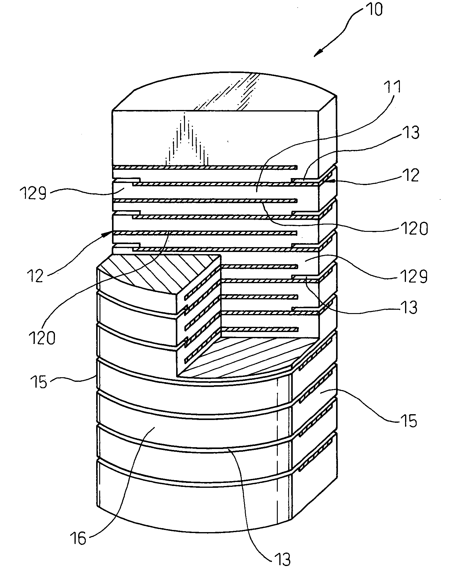
[0009] The present invention was achieved by considering said current problem, and provides a laminate-type piezoelectric element with high durability and a little possibility of causing problems such as cracks over a long term.

Problems solved by technology

However, there is the following problem in said current laminate-type piezoelectric element.
More specifically, there is a problem that stress, according to a piezoelectric displacement of said laminate-type piezoelectric element, concentrates at non-pole parts, wherein said internal electrode parts do not exist at the inside near outer peripheral parts, and displacement due to a piezoelectric effect does not occur.
On that account, there have been cases where cracks, etc. were caused between layers of said ceramic laminate, due to concentration of the stress, when the laminate-type piezoelectric element was used for a long period.
Therefore, it was not easy to obtain both of high performance and high durability in current laminate-type piezoelectric element.

Method used


Image

  • Laminated-type piezoelectric element and a manufacturing method thereof
  • Laminated-type piezoelectric element and a manufacturing method thereof
  • Laminated-type piezoelectric element and a manufacturing method thereof

Examples


example 1

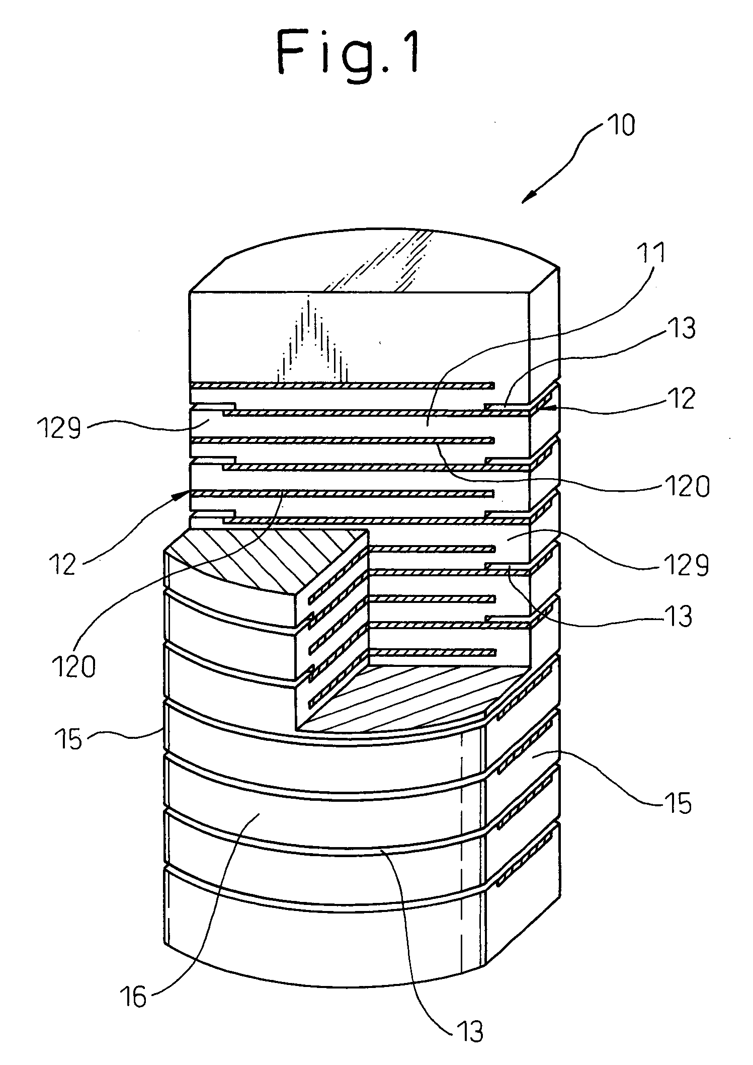
[0080] This example relates to a laminate-type piezoelectric element 1 comprising stress relaxation parts 13 for relaxation of stress being caused at the time of piezoelectric displacement, and a method for manufacturing thereof. Contents of them are explained below, by using FIGS. 1-13.

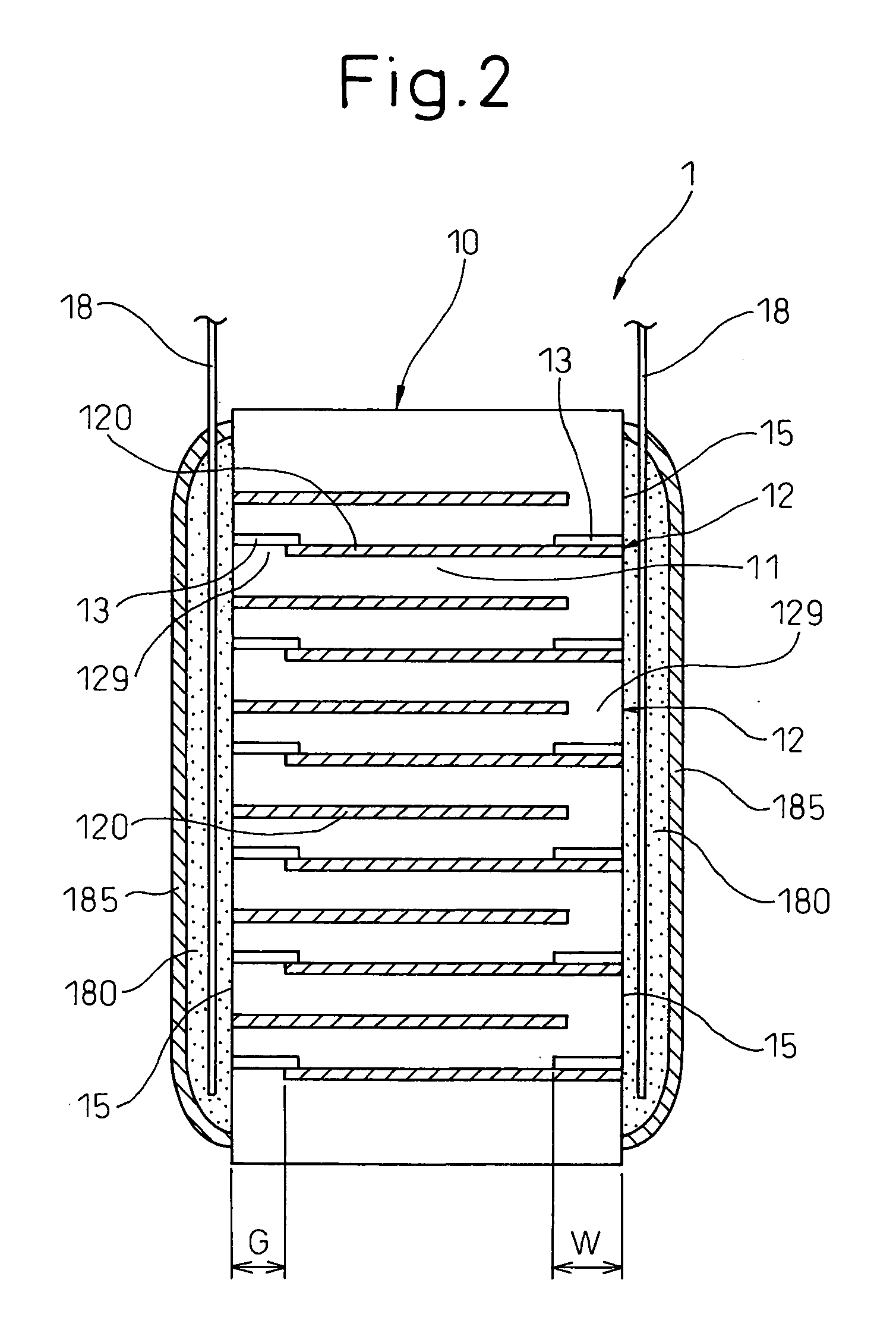
[0081] As shown in FIG. 1 and FIG. 2, the laminate-type piezoelectric element 1 of this Example comprises a ceramic laminate 10 formed by stacking ceramic layers 11 and internal electrode layers 12 in alternate order, and a pair of external electrodes 18 respectively connected with a pair of connecting areas 15 formed on outer peripheral area of the ceramic laminate 10.

[0082] Each of said internal electrode layers 12 comprises, as shown in FIG. 1, an internal electrode part 120 with electric conductivity, and a non-pole part 129 where the internal electrode part 120 does not exist at the inside near an outer peripheral area of the ceramic laminate 10.

[0083] Said ceramic laminate 10 comprises stres...

example 2

[0151] This Example is an example, based on the ceramic laminate of Example 1, and modifying a shape for placing the stress relaxation parts in a stacking sectional area. The content of this Example is explained below, by using FIGS. 14-19.

[0152] In said stress relaxation material placing step of this Example, as shown in FIG. 14, the stress relaxation material 33 is not placed in one straight part 521, for ceasing the electrode material 31, of a pair of straight parts 521 at the cut-out area 52 in shape of a barrel.

[0153] Therefore, in said cutting-out step as a later process, if the cut-out area 52 applied said stress relaxation material placing step is cut out, after applying the same electrode placing step as Example 1, as shown in FIG. 15, a sheet piece 26 can be obtained, including the electrode material, in which the stress relaxation material 33 is placed at the outer peripheral part except for said one straight part 521 (see FIG. 14), along a layer forming the internal el...

example 3

[0165] This Example is an example where the stress relaxation parts of the ceramic laminate in Example 1 or Example 2 are formed with a porous ceramic material. The content of this Example is explained below, by using FIG. 20 and FIG. 21.

[0166] In this Example, as shown in FIG. 20, the stress relaxation material 33 is used, which was formed by dispersing carbon particles 333 as the vanishing material in the slurry composed of the ceramic material in Example 1, in place of the stress relaxation material consisting of only the vanishing material.

[0167]FIG. 20 shows a magnified sectional structure around a part, where the stress relaxation material 33 is placed, in the intermediate laminate 30, and FIG. 21 shows a magnified sectional structure around the stress relaxation part 13 in the ceramic laminate 10.

[0168] In this Example, as shown in FIG. 20, carbon particles 333 with an average particle diameter of 3 μm, corresponding to about 6 times of an average particle diameter of piez...


PUM

PropertyMeasurementUnit
thicknessaaaaaaaaaa
thicknessaaaaaaaaaa
thicknessaaaaaaaaaa

Abstract

The invention provides a laminate-type piezoelectric element comprising a ceramic laminate 10 with ceramic layers 11 and internal electrode layers 12 respectively stacked alternately, and a pair of external electrodes respectively connecting with a pair of connecting areas 15 formed at an outer peripheral area of the ceramic laminate 10. The internal electrode layer comprises an internal electrode part 120 with electric conductivity, and a non-pole part 120 where the internal electrode part 120 does not exist at the inside near an outer peripheral area. The ceramic laminate 10 comprises stress relaxation parts 13 able to modify more easily their shapes than the ceramic layers 11, along at least a part of said internal electrode layers. This stress relaxation part 13 is placed so as to overlap with the non-pole part 129 of either of the internal electrode layers 12, in a stacking direction of the ceramic laminate 10.

Description

BACKGROUND OF THE INVENTION [0001] 1. Field of the Invention [0002] The present invention relates to a laminate-type piezoelectric element with a high durability, obtained by stacking ceramic layers and internal electrode layers, and a method of manufacturing the element. [0003] 2. Description of the Related Art [0004] In the past, for example, there was a laminate-type piezoelectric element using a ceramic laminate with a partial electrode structure, wherein an outer peripheral part of each of internal electrode parts forming the internal electrodes layer is not exposed at a connecting area for connecting the external electrode (e.g. Japanese unexamined patent publication No. 2003-205511). [0005] Further, in order to improve the reliability of electrical insulation at an outer peripheral area of the ceramic laminate, for example, there is a laminate-type piezoelectric element in which the outer peripheral part of the internal electrode part is not exposed at the outer peripheral ar...

Claims


Application Information

Patent Timeline
Patent Type & Authority Applications(United States)
IPC IPC(8): H01L41/083H01L41/187H01L41/22H01L41/273H01L41/297H01L41/339H01L41/43
CPCH01L41/273H01L41/0838H10N30/508H10N30/053
Inventor IWASE, AKIOITO, TETSUJIOOSHIMA, TOSHIOKADOTANI, SHIGE
Owner DENSO CORP
Learn More