Power supply unit

a power supply unit and power supply technology, applied in emergency power supply arrangements, electrical appliances, electric vehicles, etc., to achieve the effect of reducing or completely eliminating idle losses

Inactive Publication Date: 2005-08-04
SIEMENS AG OESTERR
View PDF2 Cites 55 Cited by
  • Summary
  • Abstract
  • Description
  • Claims
  • Application Information

AI Technical Summary

Benefits of technology

[0017] One object of the invention now lies in creating a charger...

Problems solved by technology

Although this voltage may be far below the rated voltage and not be sufficient to operat...

Method used


Image

  • Power supply unit
  • Power supply unit
  • Power supply unit

Examples


Embodiment Construction

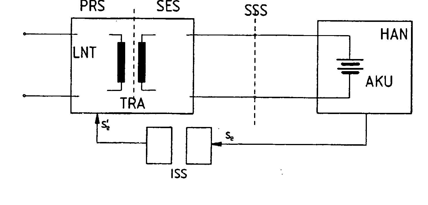
[0037]FIG. 2 shows a charger LNT which for example is embodied like the one shown in FIG. 1 as a switched-mode power supply and possesses a transformer TRA separating the primary side PRS lying on the power network from the secondary side SES. Via a plug-in interface SSS, e.g. a multipin interface usual with mobile telephones, the output voltage of the charger LNT is fed to the battery AKU of a device HAN. The invention now make provision, when the connection to the plug-in interface SSS is established e.g. plugging the charger connector into a mobile phone, for a switch-on signal Se to be derived or generated from the residual voltage of the battery AKU and forwarded via an isolating interface ISS from the secondary circuit SES as the primary switch-on signal se′ to the primary circuit PRS in order to activate the charger LNT.

[0038] As is to be explained below on the basis of the exemplary embodiments in accordance with FIGS. 3 to 9, the switch-on signal Se can be a one-off pulse ...


PUM


Abstract

A charger (LNT) for a battery-fed electrical/electronic device (HAN), with an electrically isolating transformer (TRA), which can be fed at its primary circuit and of which the secondary circuit features a converter/rectifier (GLR) to supply a charge voltage for the battery (AKU) of the device, where charger and device can be connected via a plug-in electrical interface (SSS), and. when the connection is established to the plug-in interface (SSS) a switch-on signal (se) can be derived from the residual voltage of the battery (AKU), which can be forwarded via an isolating interface (ISS) from the secondary circuit (SES) to the primary circuit (PRS) to activate the charger (LNT).

Description

CROSS REFERENCE TO RELATED APPLICATIONS [0001] This application is the US National Stage of International Application No. PCT / AT03 / 00119, filed Apr. 28, 2003 and claims the benefit thereof. The International Application claims the benefits of Austrian application No. 737 / 2002 filed May 14, 2002, both applications are incorporated by reference herein in their entirety.FIELD OF INVENTION [0002] The invention relates to a charger for a electrical / electronic device powered by rechargeable batteries with an electrically isolating transformer, the primary circuit of which can be fed from an ac mains power circuit and the secondary circuit of which features a converter / rectifier to deliver a charge voltage for the battery of the device, where charger and device can be connected via a plug-in electrical interface. BACKGROUND OF INVENTION [0003] This type of charger is known in many variants and is widely used, especially for mobile telephones, laptop and handheld computers, small household ...

Claims


Application Information

Patent Timeline
IPC IPC(8): H02J9/00
CPCH02J9/005
Inventor SCHWEIGERT, HARALD
Owner SIEMENS AG OESTERR
Why Eureka
Try Eureka