Plasma display apparatus and driving method thereof

a technology of display apparatus and driving method, which is applied in the direction of color television details, television systems, instruments, etc., can solve the problems of unstable operation, screen flicker, and difficulty in producing stable displays, so as to achieve stable operation, increase brightness, and increase the voltage margin of the driving signal required for stable operation

Inactive Publication Date: 2005-08-04
SONY CORP
View PDF0 Cites 2 Cited by
  • Summary
  • Abstract
  • Description
  • Claims
  • Application Information

AI Technical Summary

Benefits of technology

[0013] It is an object of the present invention to stabilize the operation of a plasma display apparatus and thereby improve brightness and picture quality. According to a first aspect of the present invention, there is provided a plasma display apparatus including: a panel including a dischargeable gas sealed between a pair of substrates joined to each other, a first electrode and a second electrode formed on one substrate in correspondence with each scanning line, and a third electrode formed on the other substrate in correspondence with each data line; and a driving unit for driving the first electrode, the second electrode, and the third electrode, sequentially writing and retaining data at an intersection of each scanning line and each data line, and thereby displaying one field of image.
[0019] The first frequency is controlled to be low and the frequency thereafter is controlled to be high, for example. With a first low-frequency pulse, initial discharge in a sustaining period is started stably, and with a high-frequency pulse thereafter, the discharge is sustained. Use of the high-frequency pulse increases the number of light emissions, thus leading to improvement in brightness. Since the low-frequency pulse is used in a first part of the sustaining period, the sustained discharge itself can be started stably. It is to be noted that more than two frequencies may be applied.
[0020] Thus, the present invention makes it possible to achieve both discharge stabilization and increase in brightness, and therefore the present invention can contribute to improvement in picture quality of the plasma display apparatus. Incidentally, in the present specification, the above method may be referred to as a two-frequency driving method.
[0024] The first voltage is controlled to be high and the voltage thereafter is controlled to be low, for example. By thus setting the voltage level of the driving signal in two steps, a voltage margin of the driving signal required for stable operation can be increased.
[0025] It is thereby possible to perform stable operation. It is to be noted that the voltage level of the applied signal may be set in more than two steps. In addition, even when the pulse frequency of the driving signal is raised to increase brightness, it is possible to perform driving without flicker. After sustained discharge is started stably at the first high voltage level, the voltage level of subsequent pulses can be lowered, thus leading to low radiation and low power consumption.

Problems solved by technology

In the case of a least significant bit, in particular, an effective time width included in the sub-field period is extremely short, and therefore it is difficult to produce a stable display.
However, simply raising the pulse frequency of the driving signal results in susceptibility to unstable operation, screen flicker, and inability to display correct gradation levels.

Method used


Image

  • Plasma display apparatus and driving method thereof
  • Plasma display apparatus and driving method thereof
  • Plasma display apparatus and driving method thereof

Examples


Embodiment Construction

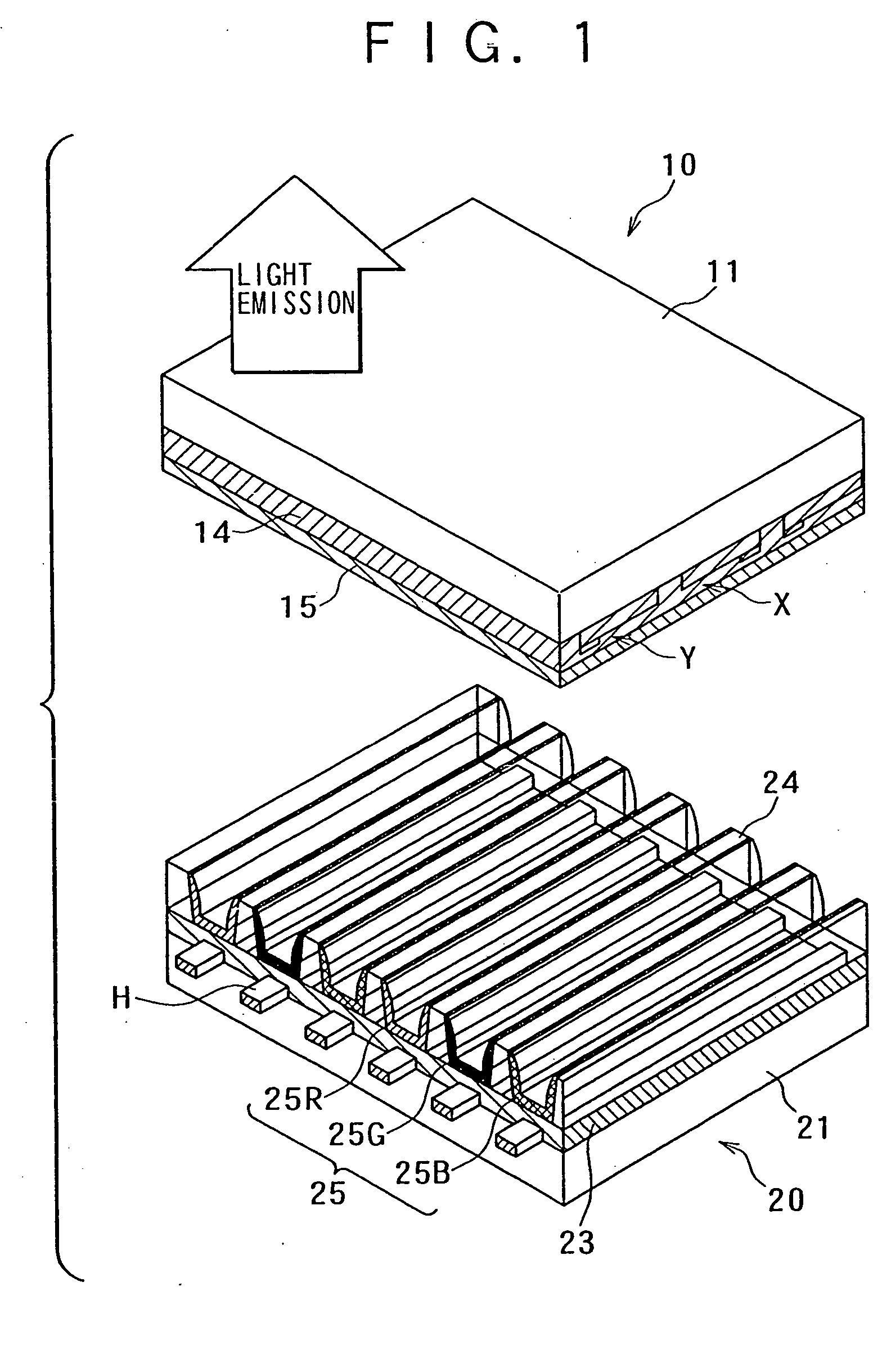
[0040] Preferred embodiments of the present invention will hereinafter be described in detail with reference to the drawings. As shown in FIG. 1, a plasma display apparatus according to the present invention is of an AC type and of a three-electrode type. The plasma display apparatus is formed with a front panel 10 and a rear panel 20 joined to each other at peripheral portions thereof. Light emission of a phosphor layer 25 on the rear panel 20 is observed through the front panel 10.

[0041] The front panel 10 includes: a transparent glass substrate 11; a plurality of pairs of scanning electrodes Y and sustaining electrodes X formed of transparent conductive material and disposed in a stripe manner on the glass substrate 11; a dielectric layer 14 of dielectric material formed on the glass substrate 11 so as to cover the electrodes; and a protective film 15 of MgO or the like formed on the dielectric layer 14.

[0042] Bus electrodes of a metallic material having a low electric resistiv...


PUM


Abstract

According to a plasma display apparatus of the present invention, at least in one sub-field, a driving signal applied to retain data written in each pixel has a frequency applied first and a frequency applied thereafter, the frequencies being different from each other. The first frequency is controlled to be low and the frequency thereafter is controlled to be high, for example (two-frequency driving method). With a first low-frequency pulse, initial discharge in a sustaining period is started stably, and with a high-frequency pulse thereafter, the discharge is sustained. Use of the high-frequency pulse increases the number of light emissions, thus leading to improvement in brightness. Thus, the present invention enables both discharge stabilization and increase in brightness, and can therefore improve picture quality of the plasma display apparatus.

Description

BACKGROUND OF THE INVENTION [0001] The present invention relates to a plasma display apparatus and a driving method thereof. More particularly, the present invention relates to an improved technique of a sub-field method for gradation display. [0002] Plasma display panels (PDP) are known as image display apparatus to replace currently predominant cathode-ray tubes (CRTs). The plasma display apparatus has advantages of making it relatively easy to increase screen size and widen a viewing angle, having excellent resistance to environmental factors such as the temperature, magnetism, vibration and the like, having a long life, and the like. The plasma display apparatus is expected to be applied to wall-hung televisions for household use and to large information terminal apparatus for public use. [0003] The plasma display apparatus applies a voltage to a discharge cell in which a discharge gas such as an inert gas is sealed in a discharge space, excites a phosphor layer within the disch...

Claims


Application Information

Patent Timeline
Patent Type & Authority Applications(United States)
IPC IPC(8): H04N5/66G09G3/20G09G3/28G09G3/288G09G3/291G09G3/294G09G3/296G09G3/298
CPCG09G3/2022G09G3/2029G09G3/294G09G3/2944G09G2320/0626G09G2320/0228G09G2320/0266G09G2320/0271G09G3/2946G09G3/296
Inventor SUZUKI, YOSHIO
Owner SONY CORP
Why Eureka
Try Eureka