Liquid crystal display device
- Summary
- Abstract
- Description
- Claims
- Application Information
AI Technical Summary
Benefits of technology
Problems solved by technology
Method used
Image
Examples
embodiment 1
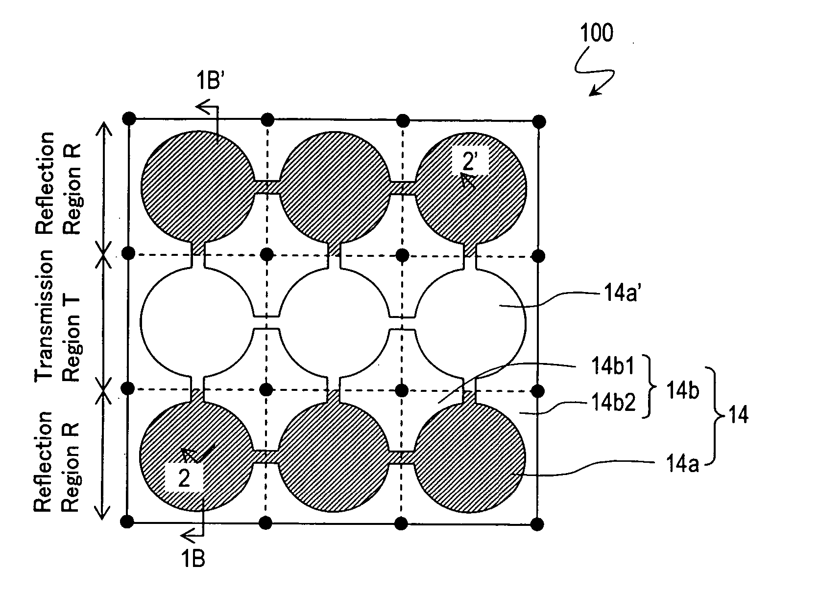
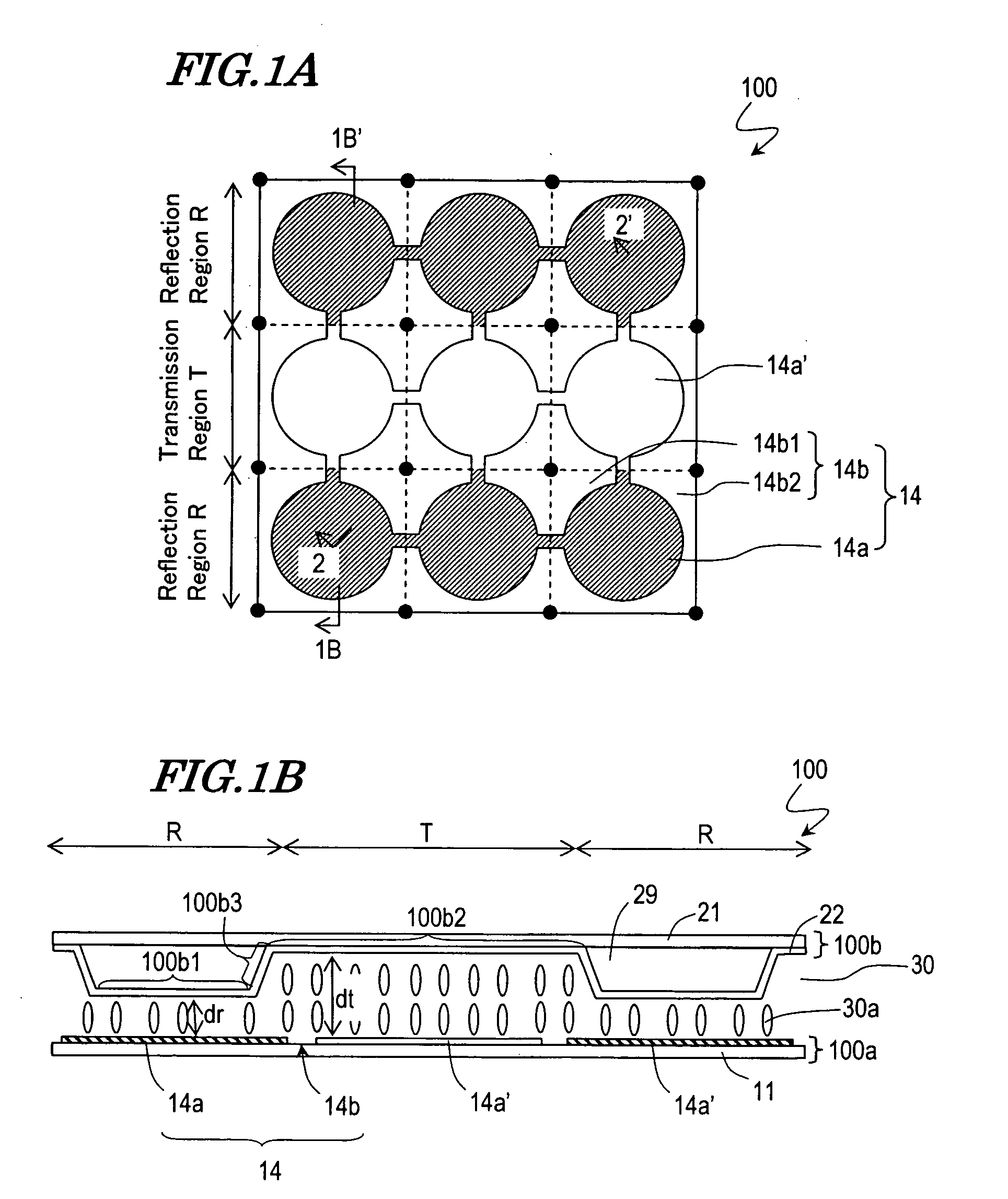
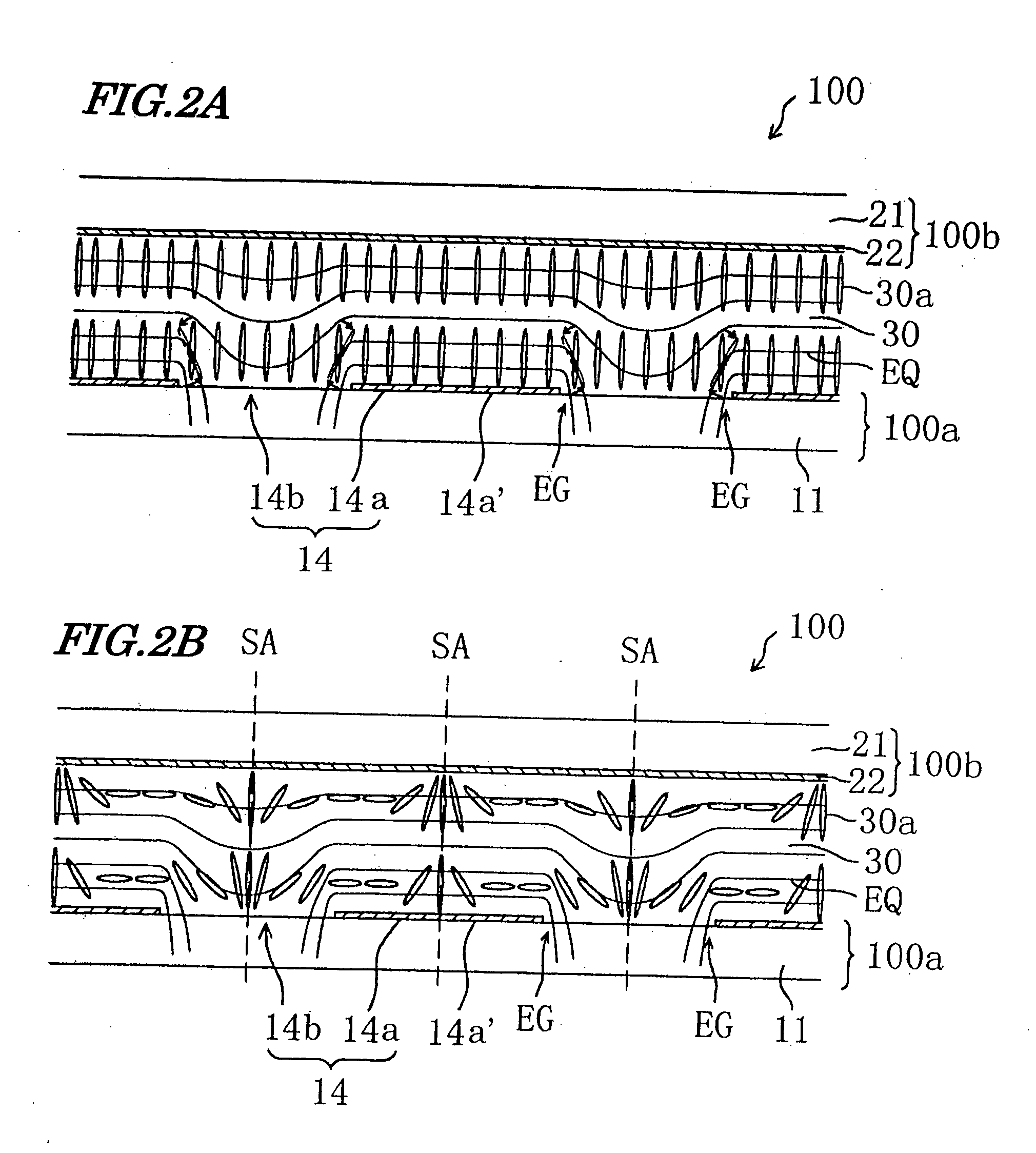
[0137] The structure of one picture element region of a liquid crystal display device 100 according to the present embodiment will now be described with reference to FIG. 1A and FIG. 1B. In the following description, a color filter and a black matrix are omitted for the sake of simplicity. Moreover, in subsequent figures, each element having substantially the same function as the corresponding element in the liquid crystal display device 100 will be denoted by the same reference numeral and will not be further described below. FIG. 1A is a plan view illustrating the picture element region of the liquid crystal display device 100 as viewed in the substrate normal direction, and FIG. 1B is a cross-sectional view taken along line 1B-1B′ of FIG. 1A. FIG. 1B illustrates a state where no voltage is applied across a liquid crystal layer.
[0138] The liquid crystal display device 100 includes an active matrix substrate (hereinafter referred to as a “TFT substrate”) 100a, a counter substrate ...
embodiment 2
[0208] The liquid crystal display device of the present embodiment is different from the liquid crystal display device 100 of Embodiment 1 in that the counter substrate includes an orientation-regulating structure.
[0209]FIG. 15A to FIG. 15E each schematically illustrate a counter substrate 200b having an orientation-regulating structure 28. Each element having substantially the same function as that of the liquid crystal display device 100 will be denoted by the same reference numeral and will not be further described.
[0210] Each of the orientation-regulating structures 28 illustrated in FIG. 15A to FIG. 15E functions to orient the liquid crystal molecules 30a of the liquid crystal layer 30 into a radially-inclined orientation. Note that the orientation-regulating structure 28 illustrated in FIG. 15A to FIG. 15D and that illustrated in FIG. 15E are different in terms of the direction in which the liquid crystal molecules 30a are to be inclined.
[0211] The direction in which the li...
embodiment 3
[0263] A liquid crystal display device 300 of the present embodiment will now be described with reference to FIG. 36. The liquid crystal display device 300 is different from the liquid crystal display device 100 illustrated in FIG. 1A and FIG. 1B in that the thickness de of the liquid crystal layer 30 at an edge portion of the unit solid area 14a′ placed in the transmission region T is smaller than the thickness dc of the liquid crystal layer 30 at a central portion of the unit solid area 14a′, as illustrated in FIG. 36.
[0264] The response speed of the liquid crystal molecules 30a is typically higher as the thickness of the liquid crystal layer 30 (cell gap) is smaller (whereby the effect of the electric field is more significant), and it is generally inversely proportional to the square of the thickness of the liquid crystal layer 30. Therefore, if the thickness de of the liquid crystal layer 30 at the edge portion (outer periphery) of the unit solid area 14a′ is smaller than the ...
PUM
 Abstract
Description
Claims
Application Information
 - R&D
- Intellectual Property
- Life Sciences
- Materials
- Tech Scout
- Unparalleled Data Quality
- Higher Quality Content
- 60% Fewer Hallucinations
Browse by: Latest US Patents, China's latest patents, Technical Efficacy Thesaurus, Application Domain, Technology Topic, Popular Technical Reports.
© 2025 PatSnap. All rights reserved.Legal|Privacy policy|Modern Slavery Act Transparency Statement|Sitemap|About US| Contact US: help@patsnap.com


